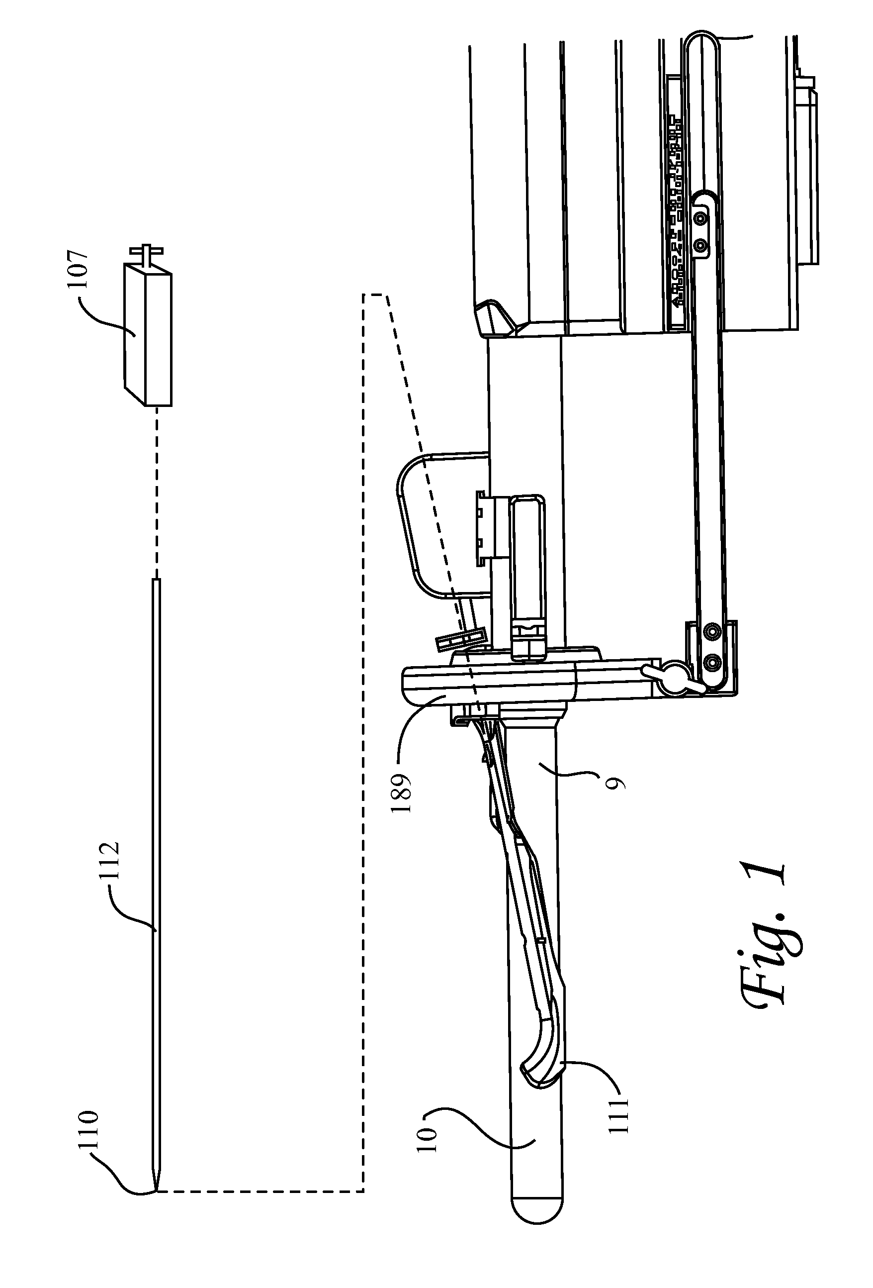
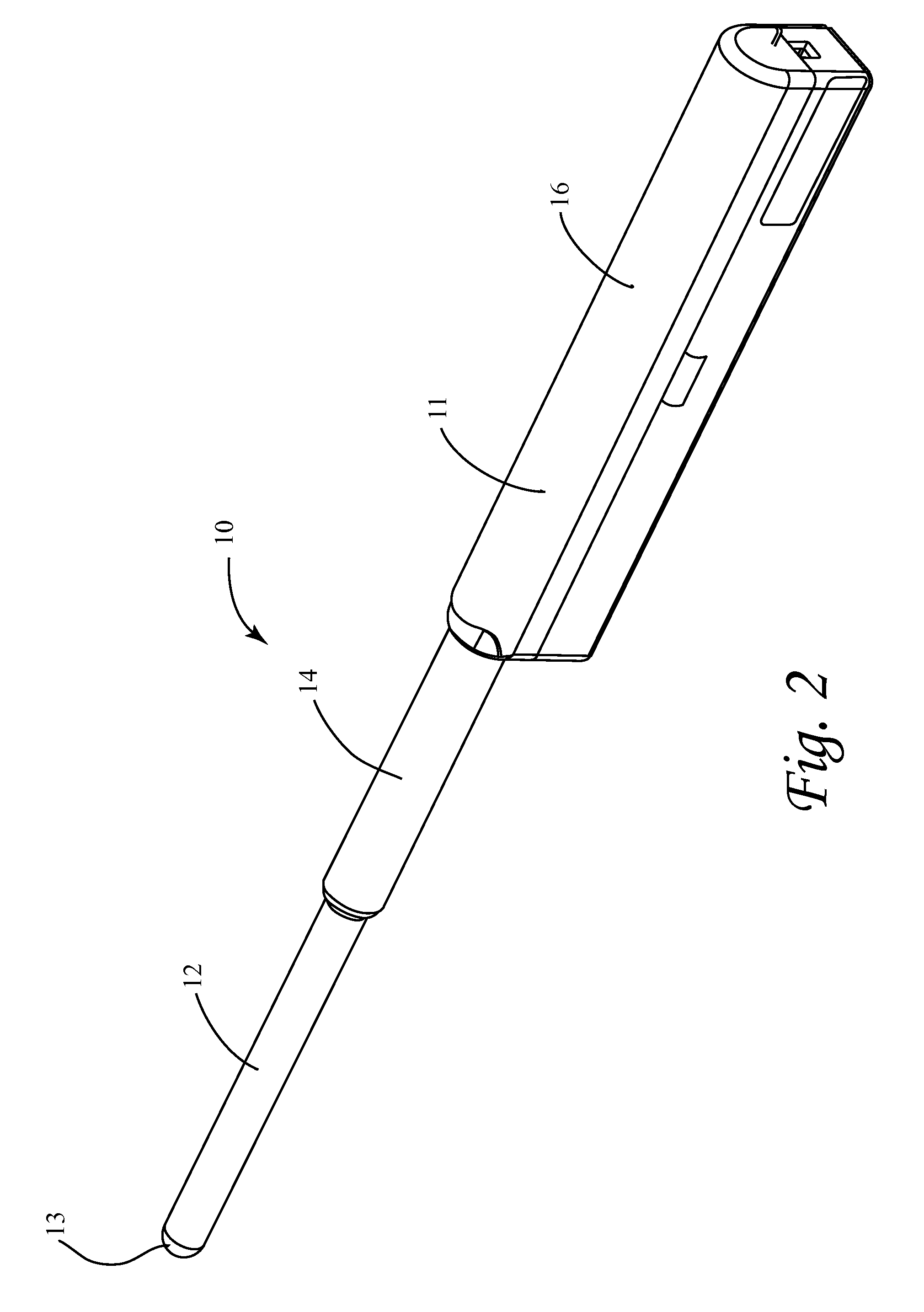
[0013]The invention is directed to an improved transrectal ultrasonic probe which is preferably utilized in conjunction with a
biopsy needle assembly and
delivery system similar to those disclosed in U.S.
patent application Ser. No. 11 / 895,228, U.S.
patent application Ser. No. 11 / 475,674, and U.S.
patent application Ser. No. ______ (Docket No. EMT-008, entitled “
Biopsy Needle
Assembly), which are herein incorporated by reference in their entireties. The improved probe allows for controlled translational and rotational movement of an ultrasonic transducer inside and across a substantially narrow distal scanning portion of the probe's housing. The narrow distal scanning portion of the probe's housing facilitates positioning and orienting the probe at different angles within the patient about the
prostate, and imaging and biopsying the
prostate. Transrectal probes commonly used in the art cause significant discomfort to the patient. The inventors have found that the transrectal probe of application Ser. Nos. 11 / 895,228 and 11 / 475,674 also cause discomfort to patients, and that the substantially narrow distal scanning section of the new improved probe reduces this discomfort. The new probe also provides structure that can be used to support and protect the coiled coax carrying the transducer
signal data.
[0014]The improved probe includes a housing which has a first elongate portion and a second elongate portion proximal of the first elongate portion. The first elongate portion is substantially narrower (e.g., has a substantially smaller cross sectional area) than the second elongate portion and is insertable into the
rectum of the patient. The first elongate portion houses an ultrasonic transducer which is capable of emitting
acoustic energy and detecting acoustic
backscatter signals. The larger second elongate portion houses a platform assembly which is rotatable relative thereto, and movable member which is both rotatable and translatable relative thereto. The platform assembly and movable member are coupled to the transducer by at least one connector extending between the first and second elongate portions of the housing such that rotational movement of the platform assembly within the second elongate portion causes rotation of the transducer within the first elongate portion, and translational movement of the moveable member within the second elongate portion causes translational movement of the transducer within the first elongate portion. The platform assembly preferably includes a
transmission system which is selectively operated to convert rotational movement of a proximally situated
drive shaft into guided translation of the moveable member relative to the platform assembly along a linear axis. In this manner, the platform assembly and at least one connector together allow for controlled translational and rotational movement of the transducer in the substantially narrower first elongate scanning portion of the housing.
[0015]In the preferred embodiment, the first and second elongate portions of the housing are fluidly coupled with each other and filled with a ultrasonic
coupling medium (e.g. clear
ultrasound transmission gel such as oil which preferably has acoustic properties similar to tissue and water). The first elongate portion of the housing is preferably made from a plastic that allows for transmission of the ultrasonic signals therethrough. Thus, the first elongate portion of the housing and the transmission gel are relatively transparent with respect to ultrasonic signals emitted by the transducer passing therethrough. The oil flows freely between the first and second elongate portions. As a result, movement of the transducer, sled, movable member, connector(s), and platform assembly within the housing causes zero net displacement of the
ultrasound coupling medium, which eliminates leakage. The volume of the first and second elongate portions of the probe is fixed. Thus, any change in net displacement of the components within the first and second elongate portions would put pressure on the seals therein, causing oil to leak out of the housing or air to be pulled into the housing, either of which can cause degradation of the image procured from the probe data.
[0017]In the preferred embodiment, a first connector is rigidly coupled to both the transducer and the movable member, and a second connector is rigidly coupled to the frame of the platform assembly and slidably coupled to the transducer. The first connector directly links translational and rotational movement of the movable member to that of the transducer. The second connector rigidly supports the transducer and guides the translation thereof, preferably parallel to the linear axis along which the movable member translates, and reduces undesired movement of the transducer during operation. In this manner, the first and second connectors transfer controlled movement of the movable member and platform assembly to the transducer within the substantially smaller scanning portion of the housing while providing support and stability to the transducer.
[0019]The guide assembly includes at least one guide channel extending between an inlet and an outlet. The inlet receives the distal end of the needle assembly (e.g., the needle and the cannula). The guide channel functions to physically bend the needle and cannula when the needle and cannula are advanced therethrough such that the distal end of the needle assembly exits the outlet of the guide channel at a desired orientation and direction. In particular, the distal section of the guide channel is curved to provide a bend angle across the distal section. When the needle assembly passes though the bend of the distal section, the distal section bends the needle and cannula such that the needle and cannula are aligned in the bent configuration with the tissue piercing distal ends of the needle and cannula disposed adjacent each other in the desired orientation and direction. In this manner, the needle and cannula are directed by the guide assembly in a predetermined controlled direction to facilitate adequate placement of the sampling section of the needle into the desired tissue to be sampled.
[0023]The improved ultrasonic probe may also be used to provide guidance during transperineal procedures including
brachytherapy, chryotherapy or other transperineal saturation biopsies in which the needle is inserted through a grid through the
perineum and transrectal images from the probe are used for guidance.
Brachytherapy is a minimally invasive treatment that administers radioactive seeds (the size of a grain of rice) directly into the
prostate, which allows the ability to use higher doses in the seeds without damaging any surrounding
healthy tissue. The radioactive seeds are placed into thin needles and directed into the prostate through the
perineum. The seeds release
low dose radiation for several weeks or months, killing the
cancer cells.
Cryotherapy uses
argon gas to freeze and
helium gas to thaw, a process which destroys
cancer cells in the prostate. A warming
catheter is inserted through the
urethra to protect it during the freezing process of the prostate. The
cancer cells in the prostate are destroyed as they thaw. The probe may also be used for guidance during laparascopic and non-laparoscopic surgeries involving other cavities such as the
abdominal cavity (e.g., surgeries involving the
small intestine,
large intestine,
stomach,
spleen, liver,
pancreas, kidneys, and adrenal glands), the
thoracic cavity, and the
pelvic cavity.


