
System and method for microfluidic cell culture

a microfluidic and cell culture technology, applied in the field of microfluidic devices, can solve the problems of nonadherent cells, dehydration, and reports of the application of programmable microfluidic systems to long-term analysis, and achieve the effects of reducing the speed of perfusion fluid

Active Publication Date: 2012-01-12
THE UNIV OF BRITISH COLUMBIA
View PDF3 Cites 55 Cited by
  • Summary
  • Abstract
  • Description
  • Claims
  • Application Information

AI Technical Summary

Benefits of technology

[0011]In a further embodiment, there is provided a method of culturing a cell, the method including: retaining the cell in a volume of perfusion fluid, wherein the volume is less than about 10 nL; and placing the volume of perfusion fluid in fluid communication with a reservoir fluid, wherein the reservoir fluid has a volume greater than the volume of perfusion fluid.
[0012]The first region of the chamber may be defined as the volume of the chamber interposed directly between the inlet and outlet positions. Furthermore, the first region is spaced apart from the retaining position such that the velocity of the perfusion fluid at the retaining position is lower than the velocity of the perfusion fluid adjacent the inlet and outlet positions during perfusion. Similarly, the first region is spaced apart from the retaining position such that the velocity of the perfusion fluid at the retaining position is lower than the velocity of the perfusion fluid within the first region during perfusion. Accordingly, the velocity of the perfusion fluid around a cell at the retaining position may be regulated such that the velocity of the perfusion fluid is lower at the retaining position than adjacent the inlet and outlet positions during perfusion. The velocity of the perfusion fluid around a cell at the retaining position may be regulated such that the velocity of the perfusion fluid is lower at the retaining position than the first region. The speed of the perfusion fluid may be decreased to less than 50 μm/s as the perfusion fluid approaches the retaining position. The speed of the perfusion fluid may be decreased to less than 40 μm/s as the perfusion fluid approaches the retaining position. The speed of the perfusion fluid may be decreased to less than 30 μm/s as the perfusion fluid approaches the retaining position. The speed of the perfusion fluid may be decreased to less than 20 μm/s as the perfusion fluid approaches the retaining position. The speed of the perfusion fluid may be decreased to less than 10 μm/s as the perfusion fluid approaches the retaining position. The speed of the perfusion fluid may be decreased to less than 5 μm/s as the perfusion fluid approaches the retaining position. The speed of the perfusion fluid may be decreased to less than 4 μm/s as the perfusion fluid approaches the retaining position. The speed of the perfusion fluid may be decreased to less than 3 μm/s as the perfusion fluid approaches the retaining position. The speed of the perfusion fluid may be decreased to less than 2 μm/s as the perfusion fluid approaches the retaining position. The speed of the perfusion fluid may be decreased to less than 1 μm/s as the perfusion fluid approaches the retaining position. The speed of the perfusion fluid may be decreased to 0 μm/s as the perfusion fluid approaches the retaining position.
[0013]The chamb

Problems solved by technology

Cell population heterogeneity poses a major obstacle to understanding complex processes that govern tissue-specific cellular responses, differentiation, and disease development.
These latter approaches indicate the power of higher throughput micro-culture systems, even though they lack desirable features including variable schedules of medium exchange.
Nature 442 , 403-411 (2006)), there have been relatively few reports of the application of programmable microfluidic systems to the long-term analysis of biological responses presumably owing to the difficulties in obtaining robust growth of mammalian cells in microfluidic devices.
Technical hurdles in available devices include dehydration, immobilization of nonadherent cells to facilitate medium exchange and recovery of the cultured cells for subsequent phenotypic or functional analysis.
In addition, small hydrophobic molecules can diffuse in the elastomeric material and be depleted from the medium.
These variations may lead to spurious biological responses, reduced growth rates and even cell death.

Method used


Image

  • System and method for microfluidic cell culture
  • System and method for microfluidic cell culture
  • System and method for microfluidic cell culture

Examples


example 1.1

Design of a Microfluidic Device for Suspension Cell Culture

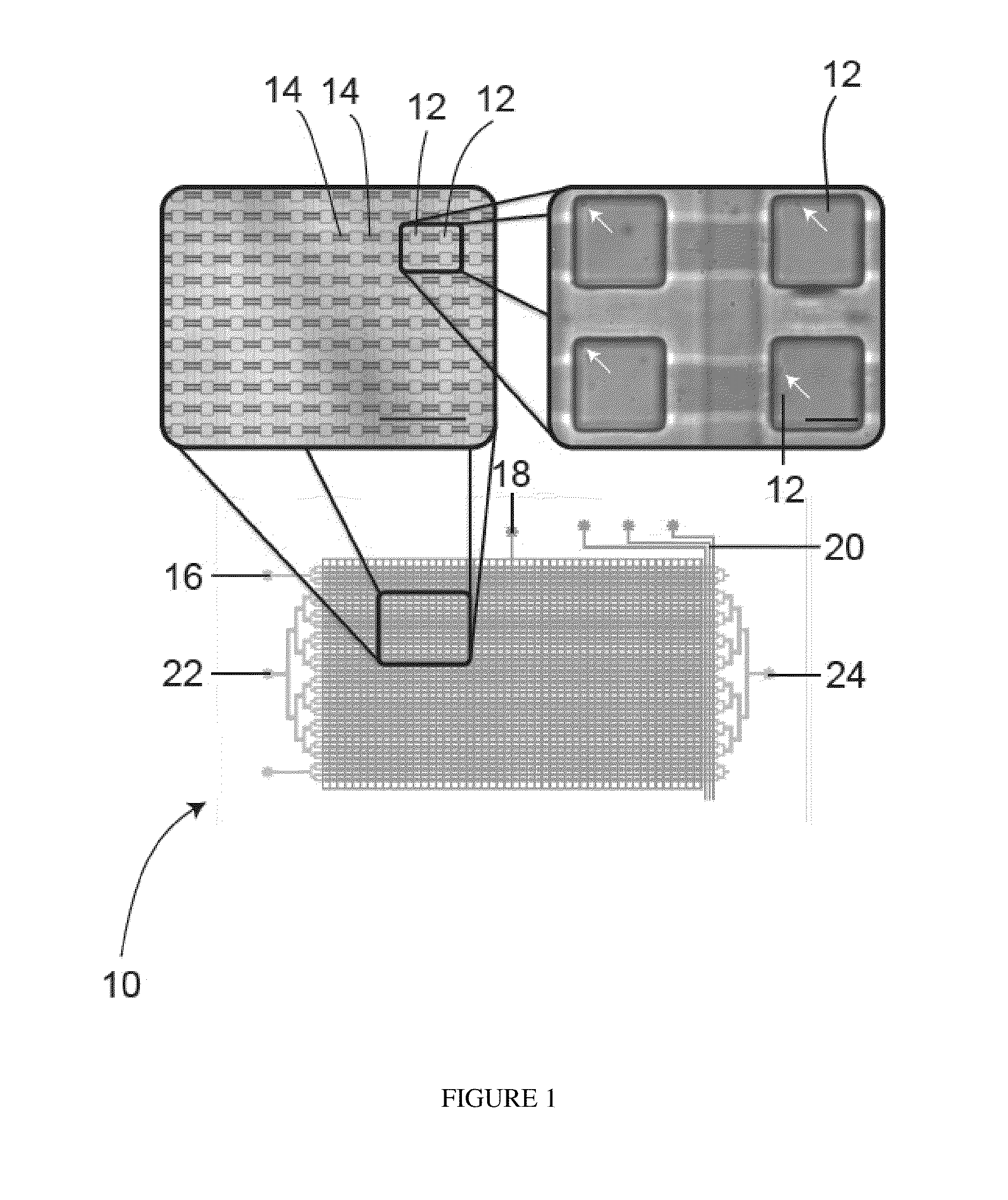
[0241]Referring to FIG. 1, a schematic drawing of a microfluidic device according to one embodiment is shown generally at 10, with micrographs as insets. The microfluidice device 10 comprises an array of 1,600 chambers 12, each having a volume of 4.1 nL with integrated microvalves to allow precise control and exchange of media. The chambers 12 are connected by flow channels 14. Hydration lines 16 are located on each side of the array to minimize edge effects. Control lines consist of an isolation valve 18 and control lines (for example, a peristaltic pump) 20 to control cell loading and perfusion rates. Fluid can be introduced to the microfluidic device 10 through an array inlet 22 in order to access the flow channels 14 and chambers 12. Fluid may leave the device through an array outlet 24. Arrows point at single cells. The left scale bar represents 1 mm and the right scale bar represents 100 μm. Alternative embodiments cou...

example 1.2

Cell Immobilization

[0243]Various embodiments allow for perfusion of cells without disturbing cell position. This capability may be exploited for experiments requiring dynamic medium exchange or immunolabeling of the cells during or at the end of an experiment. This is particularly useful for suspension cells.

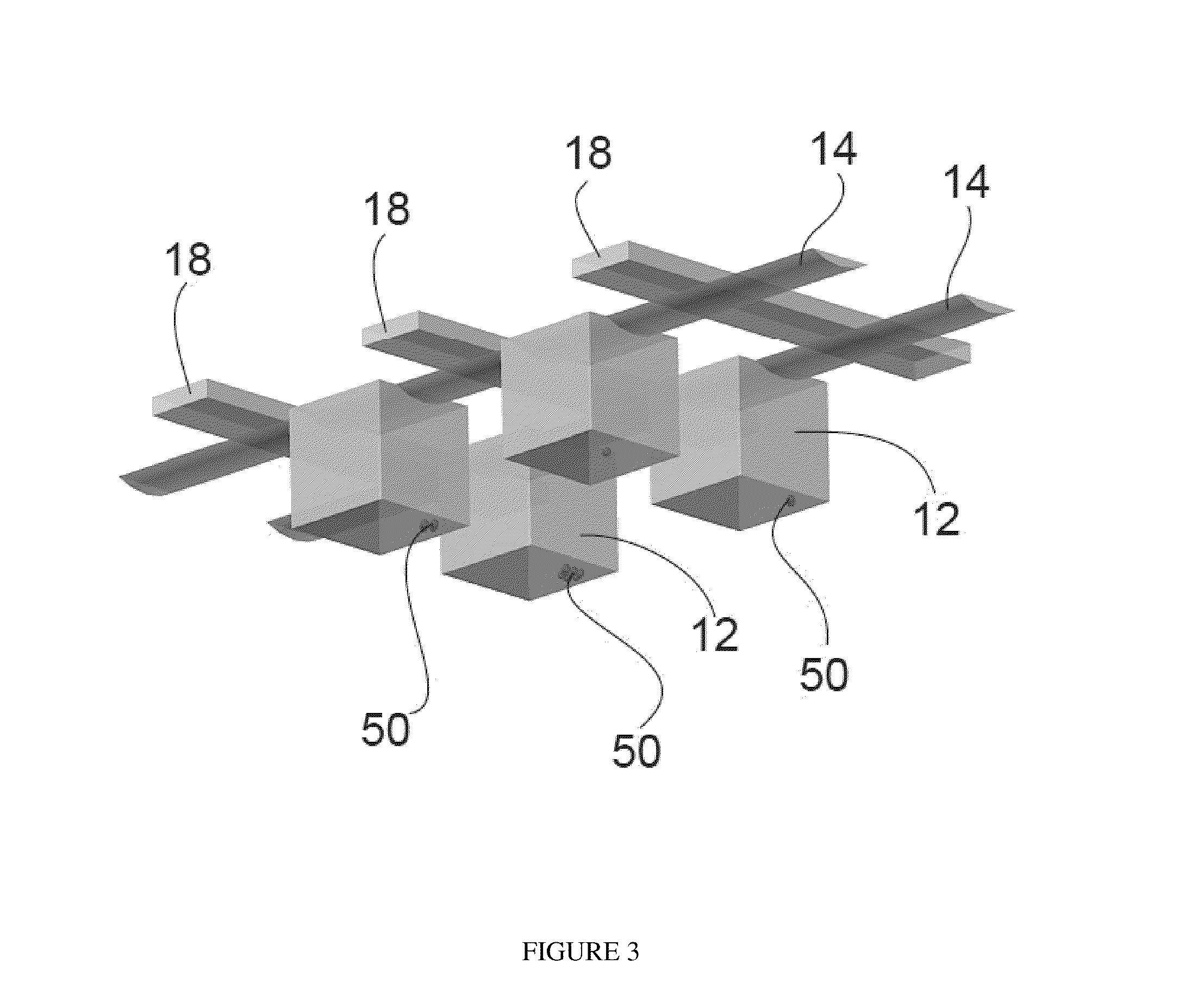
[0244]Referring to FIG. 3, one embodiment shows a microfluidic device is a non-perturbing microfluidic cell capture and retention mechanism that uses gravity to trap cells 50 in chambers with an inverted geometry with flow channels 14 running over the top and control lines 18. In the disclosed embodiment, the chambers 12 have cubic dimensions of 160 μm×160 μm×160 μm. However, larger (up to 1 mm×1 mm×1 mm) or smaller (down to 10 μm×10 μm×10 μm) could be used depending on the cell type and the intended application of the device. The chambers according to this embodiment have an aspect ratio of 1:1. However, chambers having an aspect ratio as low as 0.5 may be utilized to minimize ...

example 1.3

Culture of Hematopoietic Cells

[0251]Culture of single hematopoietic cells in microfluidic cell culture arrays. We tested the applicability of this microfluidic device to the study primitive hematopoietic cells. We first examined the growth of a preleukemic murine cells created by genetically engineering primitive adult mouse bone marrow cells to express a NUP98-HOXD13 (ND13) fusion gene9,10. Matched cultures of these “ND13” cells were set up in 24-well plates seeded at 150,000 cells / mL, 96-well plates seeded with single cells, and microfluidic cell culture arrays with or without the integrated iso-osmotic bath. In the presence of the iso-osmotic bath, the population doubling time averaged over all chambers loaded with single cells faithfully reproduced the bulk growth rate seen in the culture plates, indicating comparable conditions had been achieved. In addition, the average rates of expansion of the clones generated in the microfluidic chambers were equivalent to the average growt...


PUM


Abstract

Microfluidic devices and methods for perfusing a cell with perfusion fluid are provided herein, wherein the gravitational forces acting on the cell to keep the cell at or near a retainer or a retaining position exceed the hydrodynamic forces acting on the cell to move it toward an outlet.

Description

CROSS REFERENCE TO RELATED APPLICATIONS[0001]This application claims the benefit of U.S. Provisional Patent Application Ser. No. 61 / 362,213 entitled “SYSTEM AND METHOD FOR MICROFLUIDIC CELL CULTURE” filed on 7 Jul. 2010, which is incorporated herein by reference in its entirety.BACKGROUND[0002]1. Field[0003]This invention relates to microfluidic devices. In particular, the invention relates to microfluidic devices and their uses and methods for culturing cells for extended periods of time.[0004]2. Description of Related Art[0005]Cell population heterogeneity poses a major obstacle to understanding complex processes that govern tissue-specific cellular responses, differentiation, and disease development. Averaged measurements of large numbers of cells often obscure the variable responses of individual or rare cells. New technologies for studying cellular heterogeneity at the single cell level under well-defined chemical environments are therefore of great interest in the study of cel...

Claims


Application Information

Patent Timeline
IPC IPC(8): C12N5/0789C12M3/00
CPCC12M23/16
Inventor HANSEN, CARL L. G.LECAULT, VERONIQUEPIRET, JAMES M.
Owner THE UNIV OF BRITISH COLUMBIA
Learn More