
Image forming apparatus and method of controlling image forming apparatus

a technology of image forming apparatus and forming apparatus, which is applied in the direction of recording apparatus, digital output to print units, instruments, etc., can solve the problems of increasing the downtime of image forming on a sheet, wasteful waiting time,

Inactive Publication Date: 2012-01-12
RICOH KK
View PDF1 Cites 20 Cited by
  • Summary
  • Abstract
  • Description
  • Claims
  • Application Information

AI Technical Summary

Benefits of technology

[0009]It is an object of the present invention to at least

Problems solved by technology

Meanwhile, at the time of the image adjustment, since normal image formation is not carried out on a sheet, if the image adjustment is frequently carried out, a downtime for which image formation on a sheet is interrupted increases, and efficient image formation may not be carried out.
For this reason, in order to reflect the adjustment value obtained by detecting the test pattern in a target image, a wasteful waiting time occurs.

Method used


Image

  • Image forming apparatus and method of controlling image forming apparatus
  • Image forming apparatus and method of controlling image forming apparatus
  • Image forming apparatus and method of controlling image forming apparatus

Examples


Embodiment Construction

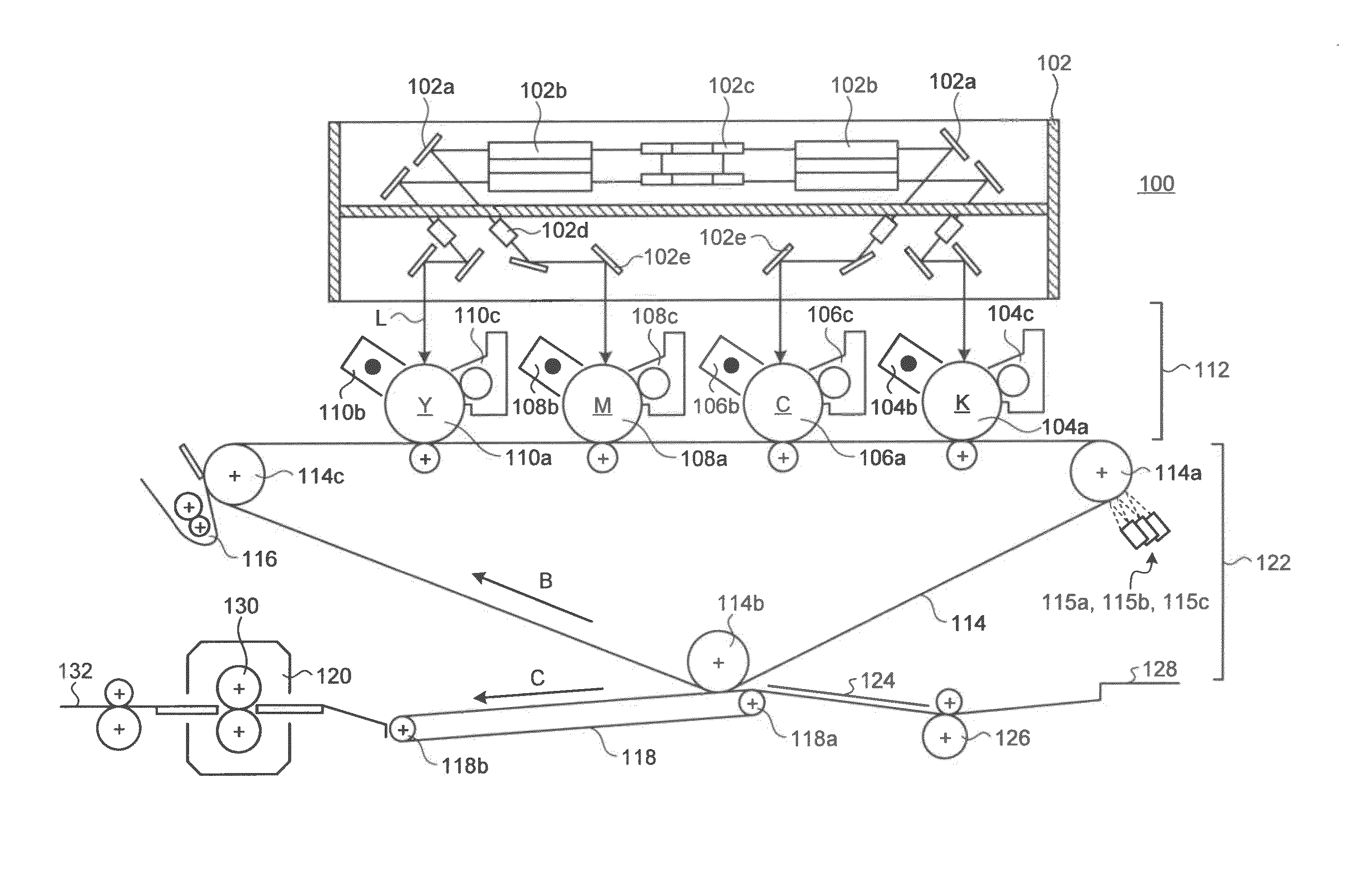
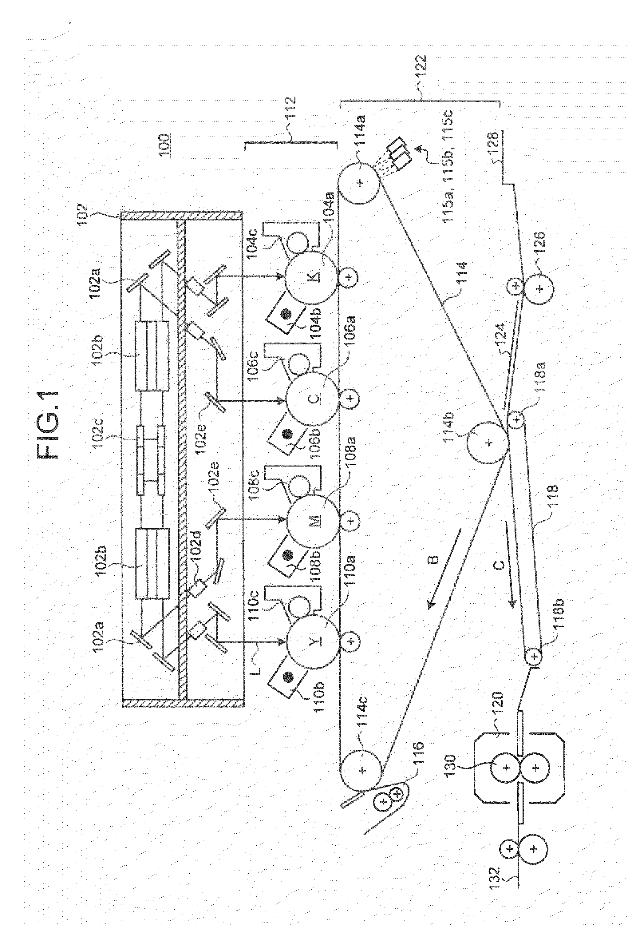
[0023]An embodiment of an image forming apparatus according to the invention will be described in detail with reference to the accompanying drawings. FIG. 1 shows an example of the structure of an image forming apparatus 100 which can be applied to the embodiment of the invention. The image forming apparatus 100 includes an optical unit 102 which includes optical elements, such as a semiconductor laser and a polygon mirror, an image forming unit 112 which includes a photosensitive element, a charging unit, a developing unit, and the like, and a transfer unit 122 which includes an intermediate transfer belt and the like.

[0024]The optical unit 102 deflects light beams emitted from a laser light source (not shown), such as a semiconductor laser, by a polygon mirror 102c and inputs the light beams to fθ lenses 102b. In the example of FIG. 1, light beams are emitted such that a number of light beams corresponds to a number of colors of yellow (Y), magenta (M), cyan (C), and black (K). Th...


PUM


Abstract

A length L of the test pattern string is determined so as to satisfy a condition L≦{P−(Q1+Q2)}×V, where a time Q is a total time of a time Q1 for which the test pattern string is transferred from an exposure position of the test pattern string to a sensor and a time Q2 from when the test pattern is detected by the sensor until a color misregistration correction value calculated on the basis of a result of detecting is reflected in image formation; a time P is a time from a timing of starting to write the test pattern string to a timing of starting to write an image in which the correction value should be reflected; and a driving speed of a second image carrier is V.

Description

CROSS-REFERENCE TO RELATED APPLICATIONS[0001]The present application claims priority to and incorporates by reference the entire contents of Japanese Patent Application No. 2010-158301 filed in Japan on Jul. 12, 2010.BACKGROUND OF THE INVENTION[0002]1. Field of the Invention[0003]The present invention relates to an image forming apparatus and a method of controlling an image forming apparatus.[0004]2. Description of the Related Art[0005]Heretofore, an image forming apparatus is known in which forming an electrostatic latent image on a photosensitive element by optical writing and primarily transferring a toner image obtained by developing the electrostatic latent image to an intermediate transfer material such as an intermediate transfer belt are carried out for each color so that the toner images of the respective colors overlap each other on the intermediate transfer material, and then the toner images of the respective colors on the intermediate transfer material are transferred ...

Claims


Application Information

Patent Timeline
IPC IPC(8): H04N1/60
CPCG03G2215/00059G03G2215/0161G03G15/0131G03G15/0194H04N1/506G03G15/011G03G15/5058
Inventor ABE, YASUHIRO
Owner RICOH KK
Learn More