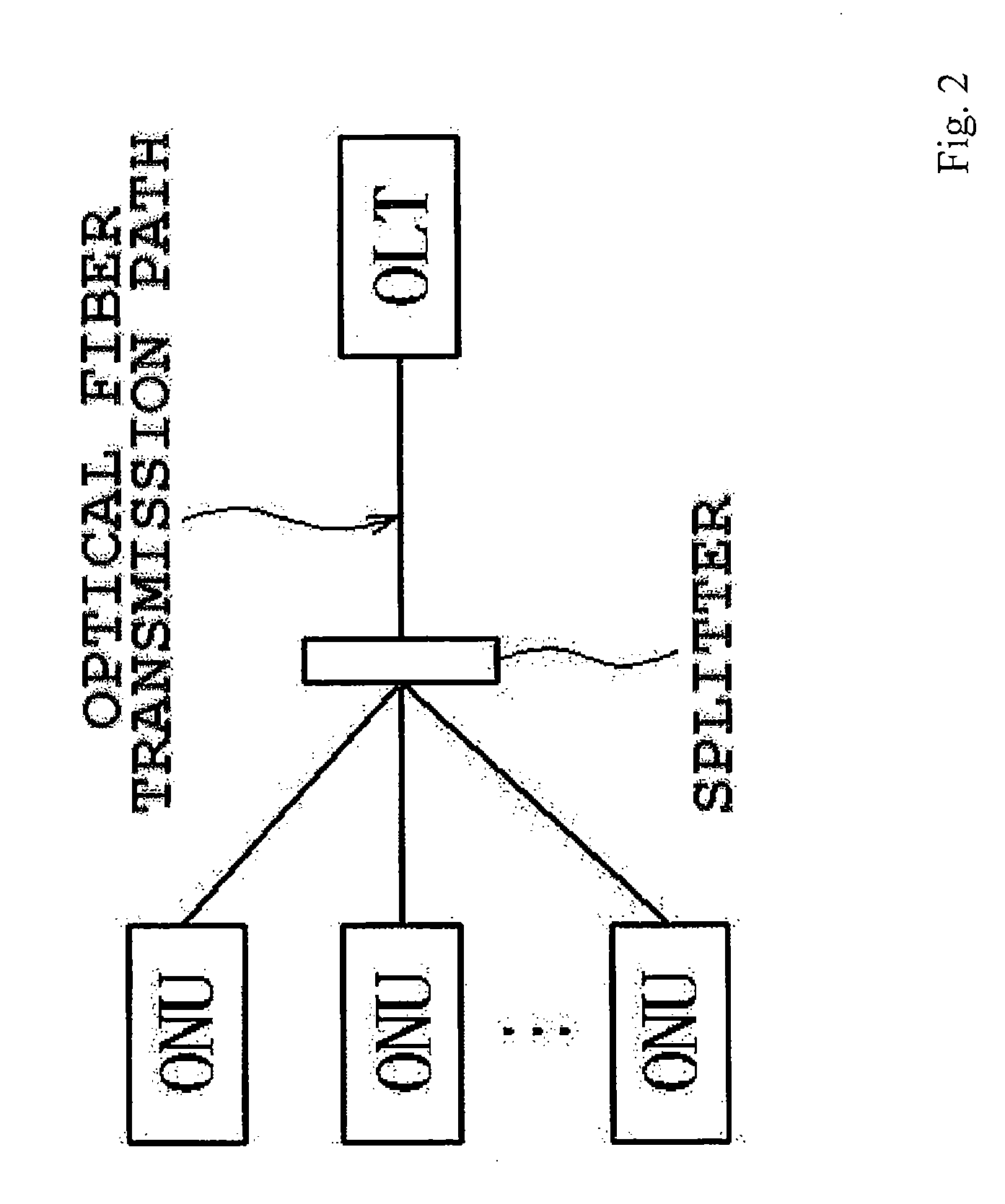
Optical line terminal and optical network unit
- Summary
- Abstract
- Description
- Claims
- Application Information
AI Technical Summary
Benefits of technology
Problems solved by technology
Method used
Image
Examples
embodiment 1-1
[0185]Hereinafter, Embodiment 1-1 that uses an optical line terminal (OLT) according to the present disclosure will be described with reference to the drawings. FIG. 5 is a functional block diagram of an OLT according to Embodiment 1-1. An OLT 10 that is illustrated in FIG. 5 includes a PON interface (PON-IF) port 1, a PON signal processing unit 2, a queue managing unit 3, a service node interface (SNI) port 4, an observing unit 5, and a calculating unit 6.
[0186]The OLT 10 includes the observing unit 5 and the observing unit 5 observes information (hereinafter, referred to as traffic information) of any one or all of an arrival interval p of frames that are transmitted to an ONU and / or received from the ONU, an instantaneous bandwidth under use B of a flow that is transmitted to the ONU and / or received from the ONU, and a queue length q of a queue that temporarily stores the frames transmitted to the ONU and / or received from the ONU. In this case, the observing unit 5 may observe on...
embodiment 1-2
[0205]Hereinafter, Embodiment 1-2 that uses an optical line terminal (OLT) according to the present disclosure will be described with reference to the drawings. FIG. 6 is a functional block diagram of an OLT according to Embodiment 1-2. An OLT 20 that is illustrated in FIG. 6 includes a PON interface (PON-IF) port 1, a PON signal processing unit 2, a queue managing unit 3, a service node interface (SNI) port 4, an observing unit 7, and a table associating unit 8.
[0206]The OLT 20 includes the observing unit 7 and the observing unit 7 observes protocol information and / or priority information of frames that are transmitted to an ONU and / or frames that are received from the ONU. The OLT 20 has a table (not illustrated in the drawings) where the priority information and / or the protocol information and the sleep time of the ONU are associated with each other. In this case, the observing unit 7 may observe only the frames that are not discarded in an ONU of an observation object. That is, ...
embodiment 2-1
[0218]First, the configuration of the ONU according to the present disclosure will be described using FIG. 9. FIG. 9 is a diagram illustrating the configuration of the ONU according to the present disclosure.
[0219][Configuration of the ONU]
[0220]An ONU 10 includes an UNI 101, a queue managing unit 11, a PON signal processing unit 12, a PON-IF 104, an observing unit 13, a stop determining unit 14, and a stopping unit 15.
[0221]The queue managing unit 11 observes a value of ToS or a value of CoS for each frame, to be described below.
[0222]The PON signal processing unit 12 includes an MPCP module 16, an OAM module 17, a MAC module 107, and a PHY module 108, and receives a sleep request message from the stop determining unit 14 to be described below. The sleep request message is transmitted to the OLT.
[0223]The observing unit 13 monitors traffic. For example, the observing unit 13 monitors an arrival interval of frames, an instantaneous bandwidth under use, and a queue length in a buffer...
PUM
 Abstract
Description
Claims
Application Information
 - R&D
- Intellectual Property
- Life Sciences
- Materials
- Tech Scout
- Unparalleled Data Quality
- Higher Quality Content
- 60% Fewer Hallucinations
Browse by: Latest US Patents, China's latest patents, Technical Efficacy Thesaurus, Application Domain, Technology Topic, Popular Technical Reports.
© 2025 PatSnap. All rights reserved.Legal|Privacy policy|Modern Slavery Act Transparency Statement|Sitemap|About US| Contact US: help@patsnap.com


