Phosphor wheel configuration for high intensity point source
a high-intensity, point source technology, applied in the field of light sources, can solve the problems of not fully optimizing the operating characteristics of prior art design parameters and/or fabrication methods, and less than desirable in some applications, and achieve the effects of compact and economical, extended life of the phosphor region, and small dimension
- Summary
- Abstract
- Description
- Claims
- Application Information
AI Technical Summary
Benefits of technology
Problems solved by technology
Method used
Image
Examples
first embodiment
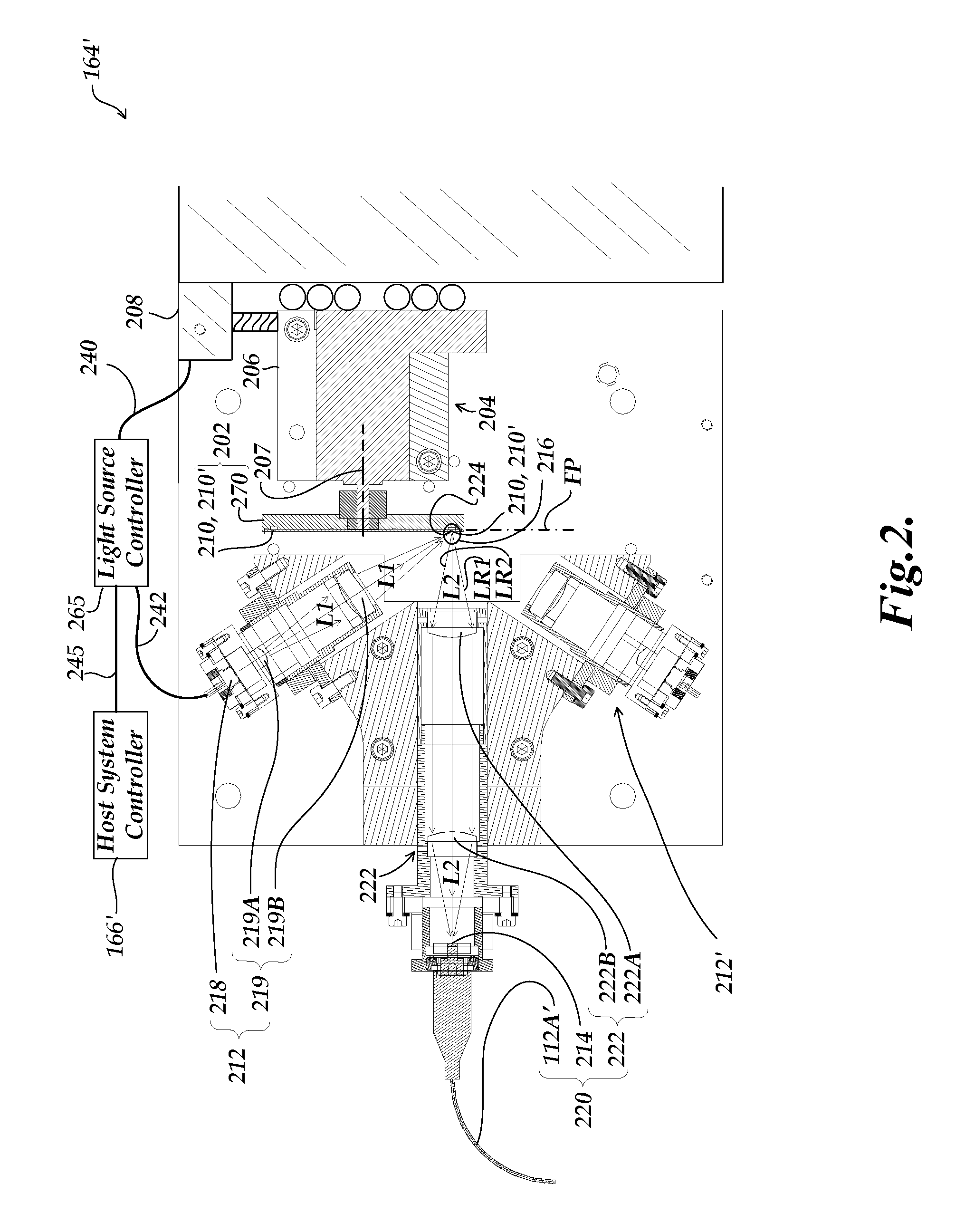
FIG. 3 is an exploded diagram of the rotary actuator 206 and a phosphor point source element 202-1 usable in place of the generic phosphor point source element 202 shown in FIG. 2. As shown in FIG. 3, the phosphor point source element 202-1 comprises a substrate 470, a phosphor region 210′-1 which includes an operational track region 210-1, and a transparent window element 211-1. The window element 211-1 is preferably as light and thin as is practical in some embodiments (e.g., it may have a thickness on the order of 500 um or less, in some embodiments), provided that the overall flatness of the window element 211-1 may be maintained in a manner consistent with the needs of various embodiments outlined below. The window element 211-1 may provide protection and / or support for the phosphor region 210′-1 in some embodiments. However, in other embodiments, it is advantageous to omit the window element 211-1, such that an input and / or output optical fiber end can be positioned proximate ...
second embodiment
FIGS. 6A and 6B are cross-section diagrams illustrating how phosphor is arranged in a tightly packed particle arrangement in a phosphor point source element 202-2. The phosphor point source element 202-2 of FIGS. 6A and 6B differs from the previously described phosphor point source element 202-1, in that instead of having an adhesive binding agent reservoir 672 that is separate from the phosphor reservoir 674, a combined reservoir 671 is used for holding both the adhesive binding agent 492 and the phosphor 494. Otherwise, the fabrication and features of the phosphor point source element 202-2 and its derivative alternative embodiments, may be understood by analogy with the previous description of the phosphor point source element 202-1.
third embodiment
FIGS. 7A and 7B are cross-section diagrams illustrating how phosphor is arranged in a tightly packed particle arrangement in a phosphor point source element 202-3. The phosphor point source element 202-3 of FIGS. 7A and 7B differs from the previously described phosphor point source element 202-1, in that the window element 211-3 is not optional, and rather than using reactive centrifugal force to create the tightly packed particle arrangement 496, a mechanical compression configuration is utilized. As illustrated in FIG. 7A, the substrate 770 includes an annular groove 777. An annular compression element 720 (e.g., a metal ring) fits snugly into the annular groove 777. A top surface of the annular compression element 720, along with the sides of the annular groove 777, form the phosphor reservoir 774. The top surface of the annular compression element 720 also functions as a phosphor track support shoulder 710, as outlined below.
As one step in fabrication, the phosphor 494 is placed...
PUM
 Abstract
Description
Claims
Application Information
 - R&D
- Intellectual Property
- Life Sciences
- Materials
- Tech Scout
- Unparalleled Data Quality
- Higher Quality Content
- 60% Fewer Hallucinations
Browse by: Latest US Patents, China's latest patents, Technical Efficacy Thesaurus, Application Domain, Technology Topic, Popular Technical Reports.
© 2025 PatSnap. All rights reserved.Legal|Privacy policy|Modern Slavery Act Transparency Statement|Sitemap|About US| Contact US: help@patsnap.com


