Spur gear power sharing gear sets

Inactive Publication Date: 2011-12-29
HARRIER TECHNOLOGIES INC
View PDF12 Cites 2 Cited by
  • Summary
  • Abstract
  • Description
  • Claims
  • Application Information

AI Technical Summary

Benefits of technology

[0006]It is an object of the present invention to provide a gear transmission that can transmit high torque when space limitations in the intended operating environment of the transmission limits the diameter of the transmission gears.
[0007]It is a further object of the present invention to provide a transmission having sets of engaging spur gears mounted on a common spline helical cut drive shaft and a common spline helical cut driven shaft wherein each spur gear set, during operational power transmission, is evenly loaded; such even loading is attained without the need of precise manufacturing tolerances; and such even loading is attained by a mechanical design which is industrially practical and cost effective to manufacture.
[0008]It is yet another object of the present invention to provide a gear transmission having sets of engaging spur gears mounted on a common spline helical cut drive shaft and a common spline helical cut driven shaft wherein even loading of each spur gear set results in reduced wear on the spur gears, thus greatly extending periods between scheduled maintenance and down time for repair.
[0010]The present invention is directed to a gear transmission having pairs of spur gears mounted on a spline helical cut drive shaft engaging pairs of spur gears mounted on a parallel spline helical cut driven shaft. In operation, the present invention obtains even load sharing among engaging and mating spur gears during power transmission.

Problems solved by technology

Transmissions that have constraints on the size of the diameter of gears due to space limitations, but which are also required to transmit significant power, have presented difficult design problems.
However, the combined load transmitted by the multiple engaging gears on a common drive shaft and a common driven shaft would be relatively large.
This apparent simple theoretical solution has proven to be impractical because of the difficulty in achieving even load sharing among engaging gears.
Due to gear manufacturing tolerances, multiple gears on a drive shaft are not likely to be perfectly aligned with the corresponding multiple gears on a driven shaft.
This non-perfect alignment results in gears on the drive and driven shaft to engage unevenly.
This results in one or more engaging sets of gears to be loaded higher than their design load with resulting premature failure due to excessive load or wear.
Minor misalignments in the drive and driven shafts and shaft flex also are factors contributing to the uneven loading of engaging multiple gears on the drive and driven shafts.
As is appreciated by one skilled in the art, the more precise the tolerances required, the greater are the manufacturing costs.
Because of these tolerance-cost considerations, transmissions having multiple gears on a drive shaft and driven shaft were generally impractical.

Method used


Image

  • Spur gear power sharing gear sets
  • Spur gear power sharing gear sets
  • Spur gear power sharing gear sets

Examples


Embodiment Construction

[0037]In order to provide a more complete understanding of the present invention and an appreciation of its advantages, a detailed description of preferred embodiments is now provided with reference to the drawings.

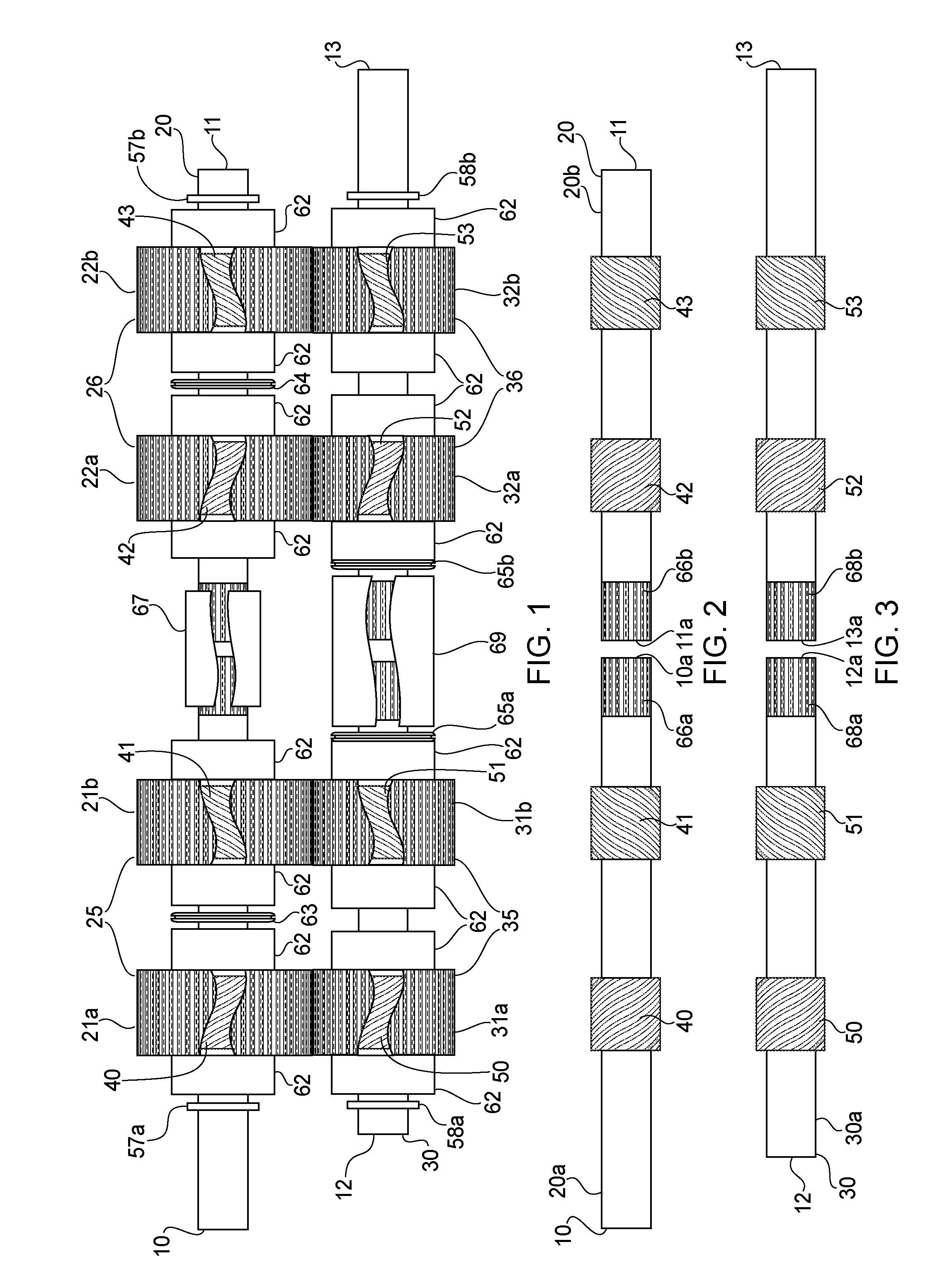
[0038]FIGS. 1, 4, 5 and 6 schematically illustrate one embodiment of a spur gear transmission in accordance with the present invention. With reference to FIGS. 1, 4, 5 and 6, there is provided a spline helical cut drive shaft 20. Spline helical cut drive shaft 20 comprises two parts 20a and 20b, as shown in FIG. 2. Spline helical cut drive shaft part 20a has a first end 10 and a second end 10a. End 10 is adapted for connection with a drive mechanism (not illustrated) for rotation of the drive shaft 20. End 10a is equipped with a straight cut spline 66a on the outer surface or diameter of the shaft. Spline helical cut drive shaft part 20b has a first end 11a and a second end 11. First end 11a is equipped with a straight cut spline 66b on the outer surface of the shaft. Spl...


PUM


Abstract

In a gear transmission, pairs of spur drive gears provided with a helical cut spline on the inner diameter of the spur drive gears are mounted on a drive shaft provided with helical cut splines on the outer diameter of the drive shaft. The pairs of spur drive gears engage pairs of spur driven gears provided with a helical cut spline on the inner diameter of the spur driven gears mounted on a driven shaft provided with helical cut splines on the outer diameter of the driven shaft. In operation, there is equal load sharing among spur drive gears engaging the spur driven gears.

Description

FIELD OF THE INVENTION[0001]The present invention is directed to improvements in load sharing amongst gears when multiple gears are mounted on a common shaft. More particularly, the present invention is directed to a gear transmission having pairs of spur gears mounted on a drive shaft equipped with helical cut splines, referred to herein as a ‘spline helical cut drive shaft’, for engagement with respective pairs of spur gears mounted on a driven shaft also equipped with helical cut splines, referred to herein as a ‘spline helical cut driven shaft’. The spur gears have a helical cut splines on their inner diameters. The result is even load sharing amongst engaging spur gears.BACKGROUND OF THE INVENTION[0002]Transmissions that have constraints on the size of the diameter of gears due to space limitations, but which are also required to transmit significant power, have presented difficult design problems. An appealing concept for the solution to this problem is the use of multiple gea...

Claims


Application Information

Patent Timeline
IPC IPC(8): F16H1/20
CPCF16H1/08Y10T74/19628Y10T74/19084
Inventor MORROW, WILLIAM BRUCE
Owner HARRIER TECHNOLOGIES INC
Why Eureka
Try Eureka