Particulate matter detection sensor and control device of controlling the same

Inactive Publication Date: 2011-12-29
DENSO CORP
View PDF0 Cites 61 Cited by
  • Summary
  • Abstract
  • Description
  • Claims
  • Application Information

AI Technical Summary

Benefits of technology

[0017]It is an object of the present invention to provide a particulate matter detection sensor of an electric resistance type and a control device of preventing particulate matter accumulated in a detection part of the particulate matter detection sensor from being remained, and further preventing the detection accuracy of the particulate matter detection sensor from being deteriorated and decreased. The particulate matter detection sensor according to the present invention outputs a stable and correct detection signal with high accuracy.

Problems solved by technology

When a quantity of particulate matter PM trapped in the DPF exceeds a predetermined allowable quantity, clogged cell walls occur in the DPF, and a pressure loss of the DPF is thereby increased.
By the way, there is a possibility of being particulate matter emitted from a previous combustion of an internal combustion engine and trapped and remained in a detection part of a particulate matter detection sensor when the engine is restarted.
However, when the detection process is executed, the temperature of the particulate matter detection sensor is within a range of 400° C. to 600° C., and this temperature is not always an adequate high temperature capable of completely eliminating remained particulate matter from the particulate matter detection sensor.
Still further, it is difficult to regenerate the particulate matter detection sensor unless an adequate period of time is elapsed.
However, there is a possibility of generating the engine stop without resetting the sensor completely.
This often causes incorrect output of the sensor after the engine restart because the characteristics of particulate matter trapped and remained in the detection part of the particulate matter detection sensor is changed by the environment during the engine stop or when the engine restart.

Method used


Image

  • Particulate matter detection sensor and control device of controlling the same
  • Particulate matter detection sensor and control device of controlling the same
  • Particulate matter detection sensor and control device of controlling the same

Examples


embodiment

[0045]A description will be given of a particulate matter detection sensor 1 and a control circuit 2 as a control device according to an embodiment of the present invention with reference to FIG. 1 to FIG. 6A, FIG. 6B and FIG. 6C.

[0046]The embodiment applies the particulate matter detection sensor 1 (hereinafter, referred to the “PM detection sensor 1”) to an exhaust gas purifying system of an internal combustion engine.

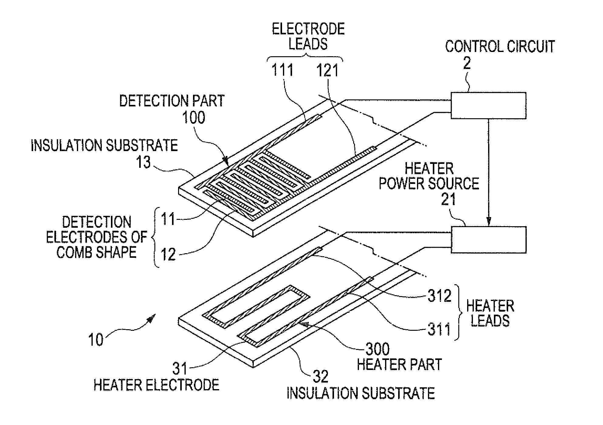
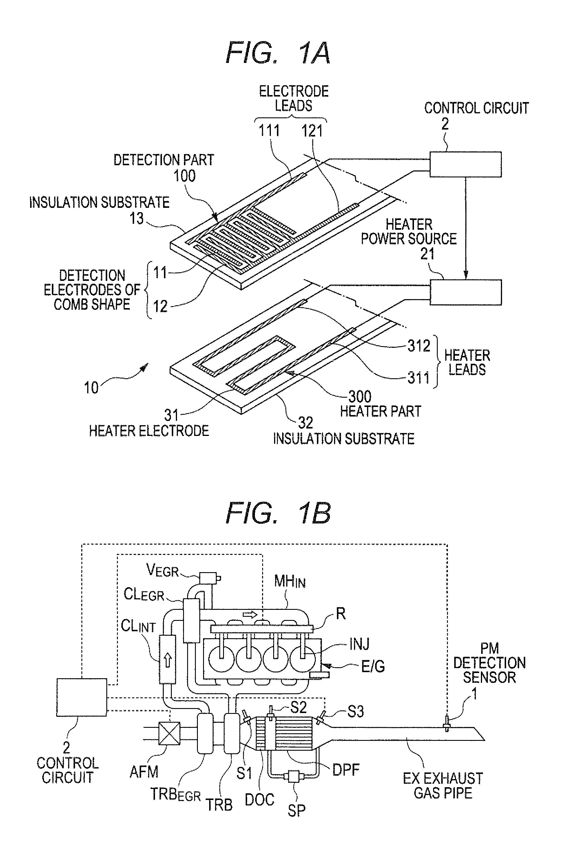
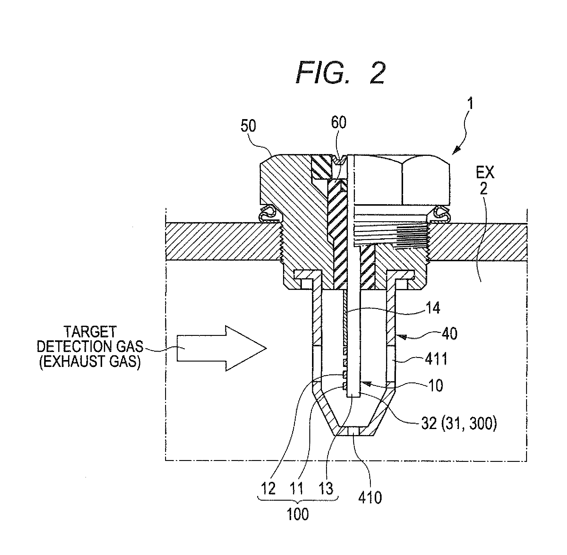
[0047]FIG. 1A is a perspective view showing a schematic structure of a particulate matter sensor element 10 (hereinafter, referred to the “PM sensor element 10”) in the PM detection sensor 1 and the control device 2 according to the embodiment of the present invention. FIG. 1B is a schematic view showing an entire configuration of the exhaust gas purifying system of an on-vehicle diesel engine of an motor vehicle to which the PM detection sensor 1 and the control device 2 according to the embodiment of the present invention are applied. FIG. 2 is an enlarged view sho...


PUM


Abstract

A particulate matter (PM) detection sensor is placed in an exhaust gas pipe of a diesel engine. The PM sensor element has a detection part composed of a pair of detection electrodes and a heater part. The detection electrodes and the heater part are stacked in the PM sensor element. A control circuit instructs a heater power supply to supply electric power to the heater part when the diesel engine is started to operate. The heater part heats the detection part at a predetermined temperature T1 within a range of 600° C. to 900° C. for a predetermined period S1 of time, for example, 650° C. for 20 seconds, in order to burn and completely eliminate particulate matter accumulated in the detection part. This control process avoids incorrect detection of the PM detection sensor. After this process, the control circuit executes usual control of the PM detection sensor.

Description

CROSS-REFERENCE TO RELATED APPLICATION[0001]This application is related to and claims priority from Japanese Patent Application No. 2010-147862 filed on Jun. 29, 2010, the contents of which are hereby incorporated by reference.BACKGROUND OF THE INVENTION[0002]1. Field of the invention[0003]The present invention relates to particulate matter detection sensors and control devices of controlling such a particulate matter detection sensor, and more particularly, particulate matter detection sensors of an electric-resistance type and control devices of detecting a quantity of particulate matter contained in target detection gas such as exhaust gas emitted from an internal combustion engine. Such a particulate matter detection sensor is placed in an exhaust gas pipe of an exhaust gas purifying system of the internal combustion engine and is applied to detecting defect of a diesel particulate filter which traps or traps particulate matters contained in the exhaust gas in order to purify th...

Claims


Application Information

Patent Timeline
IPC IPC(8): F01N3/00
CPCF01N9/002Y02T10/47G01N15/0656F02D41/1466Y02T10/40
Inventor NAKAMURA, SATOSHITERANISHI, SHINYATAKEUCHI, HIROFUMISAWADA, TAKASHIITOH, HIDEAKI
Owner DENSO CORP
Why Eureka
Try Eureka