Acoustic Wave Resonators and Methods of Manufacturing Same
a technology of acoustic waves and resonators, which is applied in the field of acoustic wave resonators, can solve the problems of unaddressed need in the art, worse q factor of smr than that of fbar, and achieve the effects of reducing the susceptibility of fbar, and reducing the cost of production
- Summary
- Abstract
- Description
- Claims
- Application Information
AI Technical Summary
Benefits of technology
Problems solved by technology
Method used
Image


Examples
first embodiment
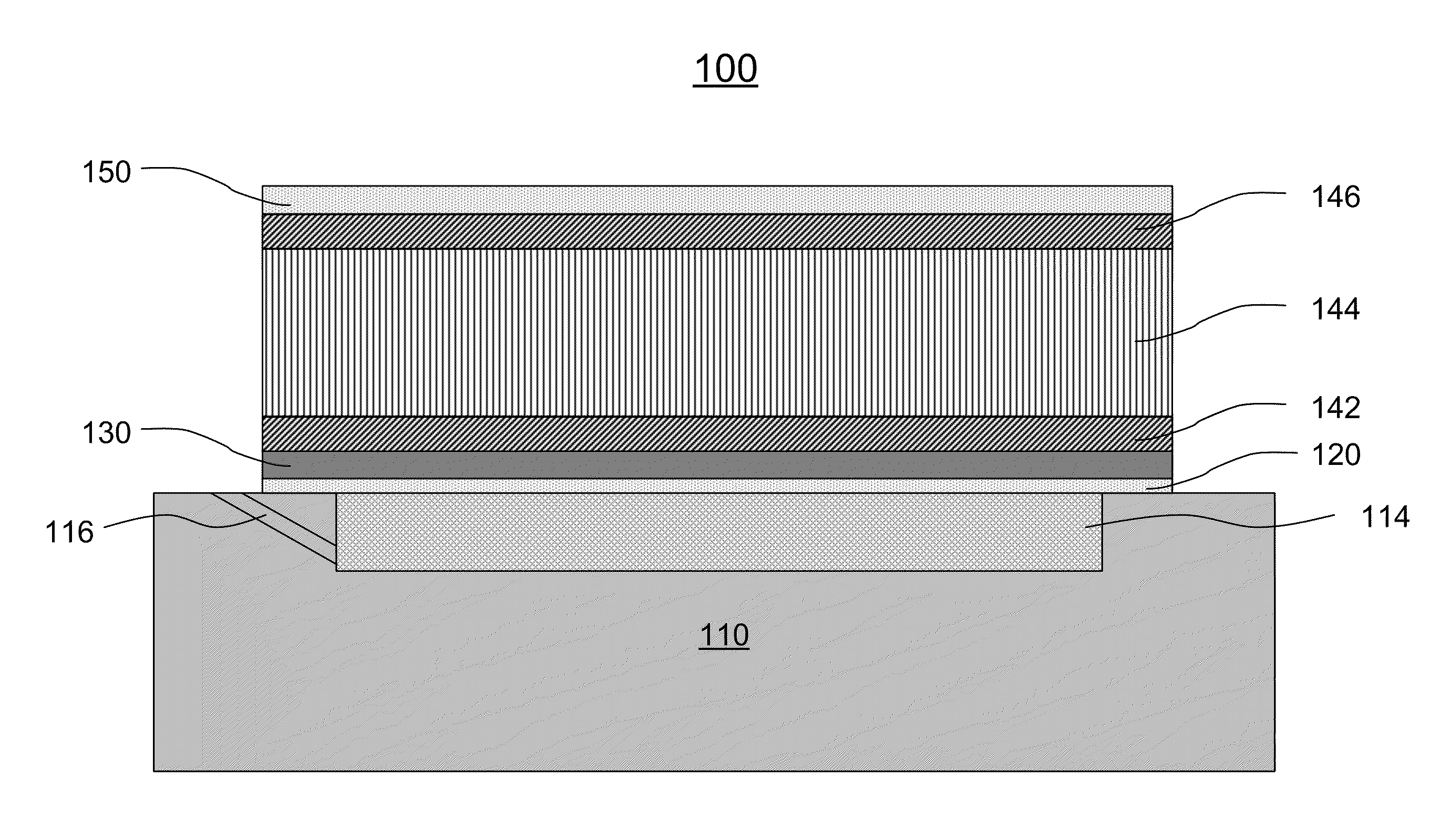
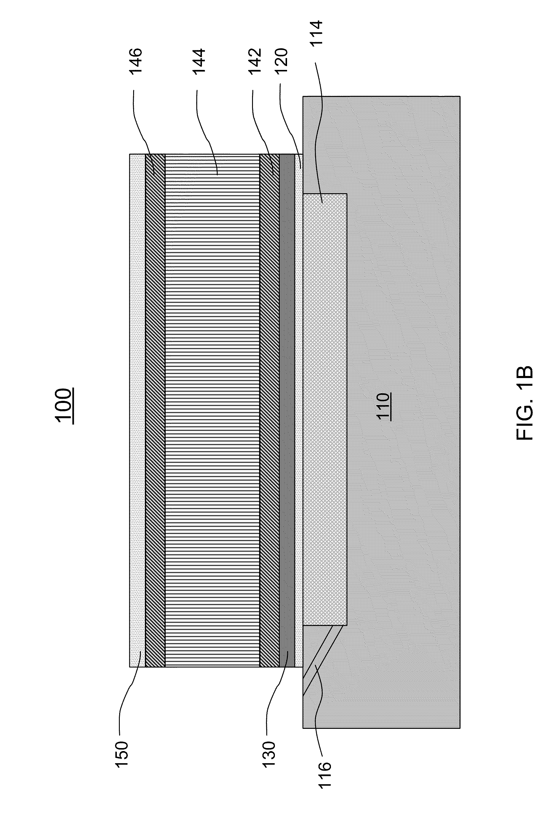
[0047]Referring to FIGS. 1A and 1B, a resonator 100 is shown according to the present invention. The resonator 100 includes a substrate 110, a first passivation layer 120 formed on the substrate 110, a seed layer 130 formed on the first passivation layer 120, a bottom electrode 142 formed on the seed layer 130, a piezoelectric layer 144 formed on the bottom electrode 142, a top electrode 146 formed on the piezoelectric layer 144 and a second passivation layer 150 formed on the top electrode 146.
[0048]The substrate 110 has an air cavity 112. The air cavity 112 is formed on a top surface of the substrate 110 or in the substrate 110. Optionally, the air cavity 112 is filled with a sacrificial layer 114 first. The sacrificial layer 114 is removed at or near the end of the fabricating process by an etching process, such as dry plasma and wet chemical etching, or other appropriate processes. In one embodiment, the sacrificial layer 114 is etched via an evacuation tunnel 116, which communi...
second embodiment
[0055]Referring to FIGS. 2A and 2B, a resonator 200 is shown according to the present invention. The resonator 200 includes a substrate 210, a first passivation layer 220 formed on the substrate 210, a seed layer 230 formed on the first passivation layer 220, a first bottom electrode 242 formed on the seed layer 230, a first piezoelectric layer 244 formed on the first bottom electrode 242, a first top electrode 246 formed on the first piezoelectric layer 244, a decoupling layer 260 formed on the first top electrode 246, a second bottom electrode 272 formed on the decoupling layer 260, a second piezoelectric layer 274 formed on the second bottom electrode 272, a second top electrode 276 formed on the second piezoelectric layer 274, and a second passivation layer 250 is formed on the second top electrode 276.
[0056]The substrate 210 includes an air cavity 212 formed on a top surface of the substrate 210 or in the substrate 210. The air cavity 212 may be filled with a sacrificial layer ...
third embodiment
[0065]Referring to FIGS. 3A and 3B, a resonator 300 is shown according to the present invention. The resonator 300 includes a substrate 310, a first passivation layer 320 formed on the substrate 310, a seed layer 330 formed on the first passivation layer 320, a bottom electrode 342 formed on the seed layer 330, a piezoelectric layer 344 formed on the bottom electrode 342, a top electrode 346 formed on the piezoelectric layer 344, and a second passivation layer 350 formed on the top electrode 346. A portion of the substrate 310 on which the first passivation layer 320 is formed is removed by an etching process from the backside of the substrate 310 to form an air cavity 312 therein.
[0066]The first passivation layer 320 is directly formed over the air cavity 312. Preferably, the first passivation layer 320 has a thickness ranging from about 10 Angstroms to about 10,000 Angstroms.
[0067]The first passivation layer 320 serves as a protective underlayer protecting the seed layer 330 from ...
PUM
| Property | Measurement | Unit |
|---|---|---|
| Thickness | aaaaa | aaaaa |
| Thickness | aaaaa | aaaaa |
| Hydrophobicity | aaaaa | aaaaa |
Abstract
Description
Claims
Application Information
 - R&D
- Intellectual Property
- Life Sciences
- Materials
- Tech Scout
- Unparalleled Data Quality
- Higher Quality Content
- 60% Fewer Hallucinations
Browse by: Latest US Patents, China's latest patents, Technical Efficacy Thesaurus, Application Domain, Technology Topic, Popular Technical Reports.
© 2025 PatSnap. All rights reserved.Legal|Privacy policy|Modern Slavery Act Transparency Statement|Sitemap|About US| Contact US: help@patsnap.com