
Acoustically powered implantable stimulating device

a stimulation device and implantable technology, applied in the field of implantable medical devices, can solve the problems of increasing the risk of infection, adding complexity to the medical procedure, and not being able to provide power or otherwise communicate with rf energy,

Inactive Publication Date: 2007-10-16
REMON MEDICAL TECH
View PDF15 Cites 172 Cited by
  • Summary
  • Abstract
  • Description
  • Claims
  • Application Information

AI Technical Summary

Benefits of technology

[0012]Although the present invention should not be so limited in its broadest aspects, the use of low-frequency acoustic energy (e.g., around 40 Khz) to energize and communication with the implantable stimulator allows the stimulator to be implanted deep within the tissue of a patient.

Problems solved by technology

Thus, RF energy may not be able to provide power to, or otherwise communicate with, an implant that is located deep within the body.
In addition, the requirement of a lead adds complexity to the medical procedure and increases the risk of infection, and in the case of pacemakers and spinal cord stimulators, increases the risk of damaging heart valves that are crossed by the lead or the spinal cord over which the lead is routed.
In some cases, the electrodes may become destabilized due to the forces applied on them by the lead.
In addition, the leads are typically composed of metal formed as a coil in which electrical current may be adversely induced in the presence of a strong magnetic field, such as that created during Magnetic Resonance Imaging (MRI).
As a result, those patients in which these leads are implanted cannot undergo an MRI.

Method used


Image

  • Acoustically powered implantable stimulating device
  • Acoustically powered implantable stimulating device
  • Acoustically powered implantable stimulating device

Examples


Embodiment Construction

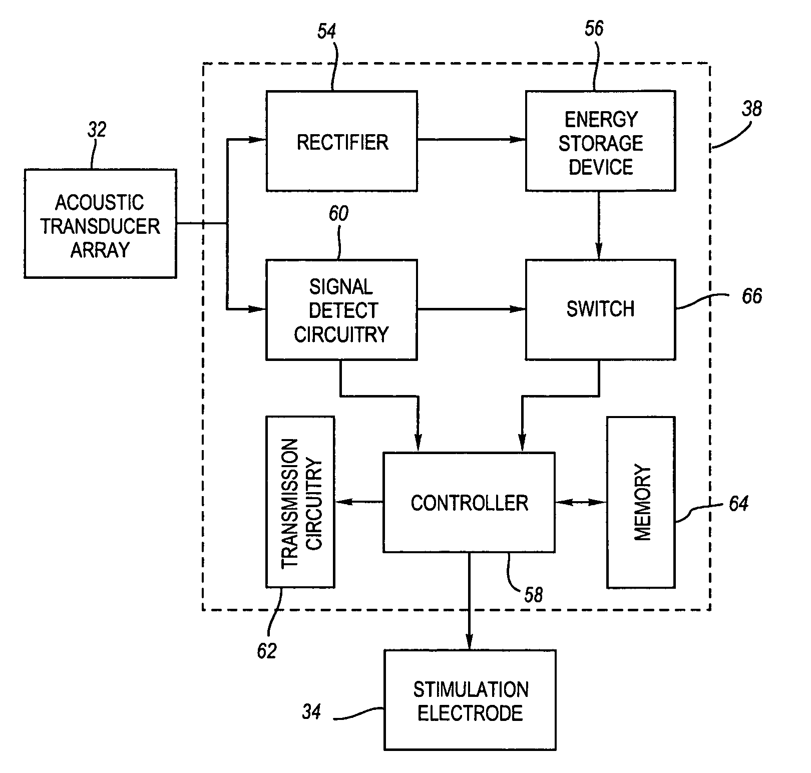
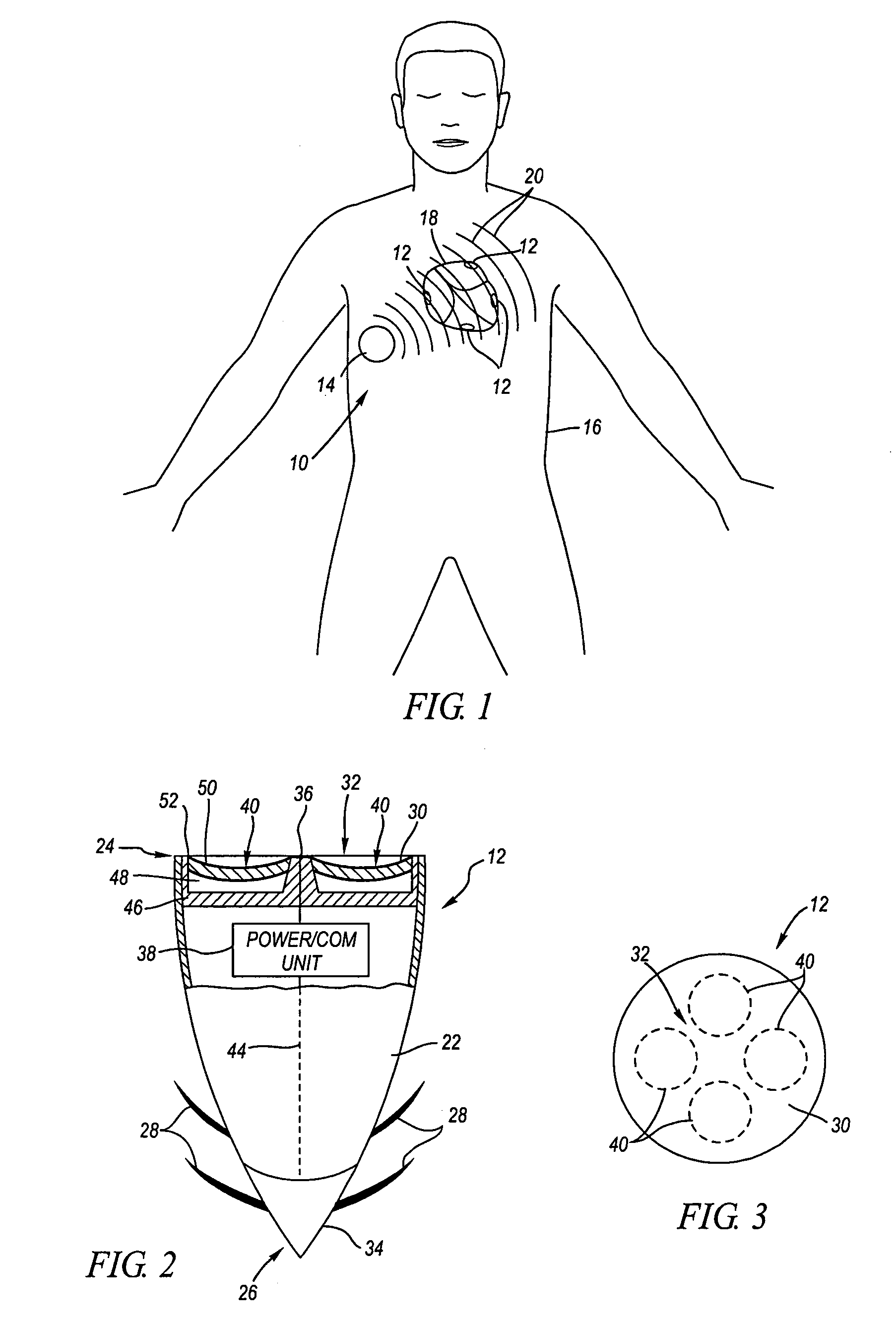
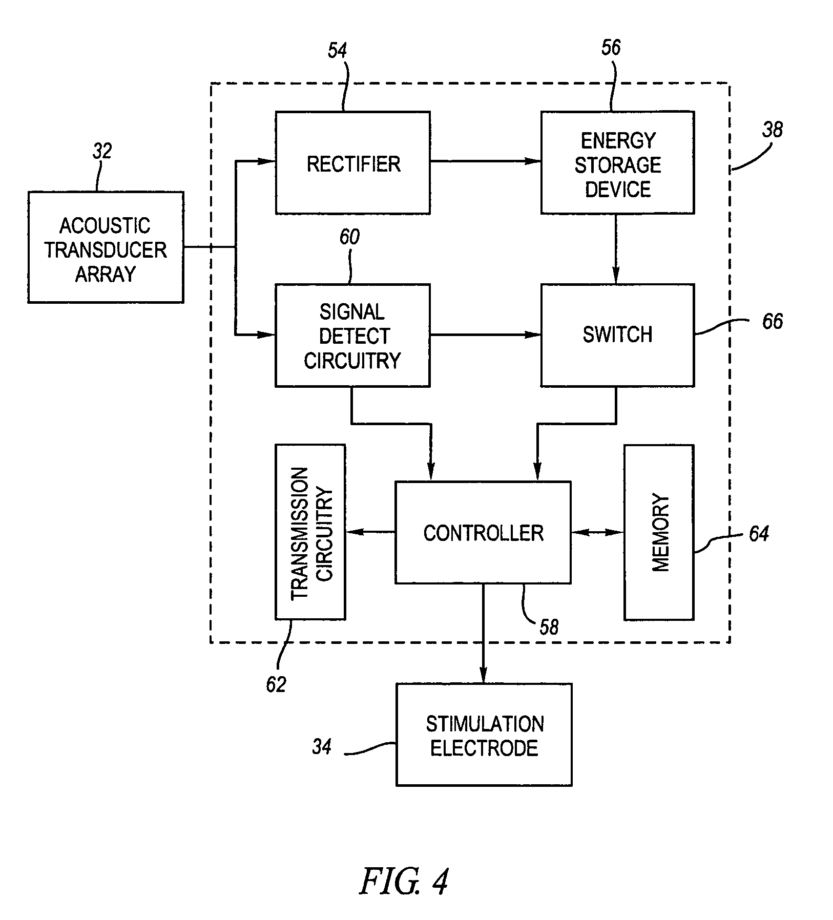
[0035]Referring to FIG. 1, an acoustic stimulating system 10 constructed in accordance with one preferred embodiment of the present invention is described. The stimulating system 10 generally comprises a plurality of implantable stimulators 12, which in this embodiment, take the form of pacemakers implanted within the heart 18 of a patient 16. The implantable stimulators 12 are implanted within the heart 18 using minimally invasive means, e.g., a catheter. The stimulating system 10 further comprises a control device 14 configured for being placed on the skin of the patient 16 in order to acoustically transmit acoustic waves 20 through the tissue of the patient 16 to the implantable stimulators 12. In the illustrated embodiment, the acoustic waves 20 can either be acoustic energizing waves or acoustic communication waves, as will be discussed in further detail below. Although, in the illustrated embodiment, the control device 14 is disclosed as an external device, an implantable cont...


PUM


Abstract

An implantable stimulation system comprises an implantable stimulator and a control device. The control device is configured to transmit acoustic waves to the implantable stimulator, and the implantable stimulator is configured to transform the acoustic waves into electrical current, and generate stimulation energy based on the electrical current. For example, the electrical current can be transformed into electrical energy that can be used to generate the stimulation energy. Or the electrical current can contain signals used to directly or indirectly control the generation of the stimulation energy.

Description

RELATED APPLICATIONS[0001]This application is (1) a continuation-in-part of U.S. application Ser. No. 09 / 989,912, filed Nov. 19, 2001 now U.S. Pat. No. 7,024,248, which is a continuation-in-part of U.S. application Ser. No. 09 / 690,615, filed Oct. 16, 2000 now U.S. Pat. No. 6,628,989; (2) a continuation-in-part of U.S. application Ser. No. 09 / 888,272, filed Jun. 21, 2001 now U.S. Pat. No. 6,764,446, which is a continuation-in-part of U.S. application Ser. No. 09 / 690,615, filed Oct. 16, 2000 now U.S. Pat. No. 6,628,989, and (3) a continuation-in-part of U.S. patent application Ser. No. 10 / 413,428, filed Apr. 14, 2003. All of these applications are expressly incorporated herein by reference.FIELD OF THE INVENTION[0002]The present invention relates generally to medical devices for implantation within a patient's body.BACKGROUND OF THE INVENTION[0003]Since the introduction of the heart rhythm control system-first as an implantable pacemaker in the 1960's, and then as an implantable defib...

Claims


Application Information

Patent Timeline
IPC IPC(8): A61N1/378A61B5/00A61B17/00A61N1/08A61N1/372
CPCA61B5/0031A61N1/3718A61N1/3787A61N1/362A61N7/00A61N1/08A61B2017/00026A61B2560/0219A61B2562/028A61N1/37217
Inventor PENNER, AVI
Owner REMON MEDICAL TECH
Learn More