
Dialysis catheter

a catheter and lumen technology, applied in the field of catheters, can solve the problems of reducing the strength of the wall, reducing the size of the lumen, and collapse of the lumen, and achieve the effect of increasing the stiffness of the catheter and facilitating insertion

Active Publication Date: 2011-12-08
ARGON MEDICAL DEVICES
View PDF5 Cites 18 Cited by
  • Summary
  • Abstract
  • Description
  • Claims
  • Application Information

AI Technical Summary

Benefits of technology

[0018]A stiffening member can be removably positionable within the catheter to temporarily increase the stiffness of the catheter to facilitate insertion. The stiffening member can be removably received in the venous lumen and can have a lumen formed therein configured to receive a guidewire therethrough. The stiffening member can extend distally of a distalmost end of the catheter body when inserted therein. The stiffening member can be secured to the catheter by a threaded engagement.
[0022]A stiffening member can be removably positionable within the venous lumen of the catheter to temporarily increase stiffness of the catheter to facilitate insertion. The stiffening member can have a lumen dimensioned to receive a guidewire.
[0026]A stiffening member can be provided removably positionable within the catheter to temporarily increase stiffness of the catheter to facilitate insertion.

Problems solved by technology

However, given the limited amount of space in the dialysis catheter, which is typically about 15-16 French, the size of the lumens is limited.
The size is also limited by the fact that if the lumens are too large, the wall thickness of the catheter becomes too thin, thereby reducing the strength of the wall and resulting in collapse of the lumens which has a detrimental affect on the blood flow.
If the lumens are too small, sufficient blood flow may not be able to be maintained and the blood can be damaged during transport.

Method used


Image

  • Dialysis catheter
  • Dialysis catheter
  • Dialysis catheter

Examples


Embodiment Construction

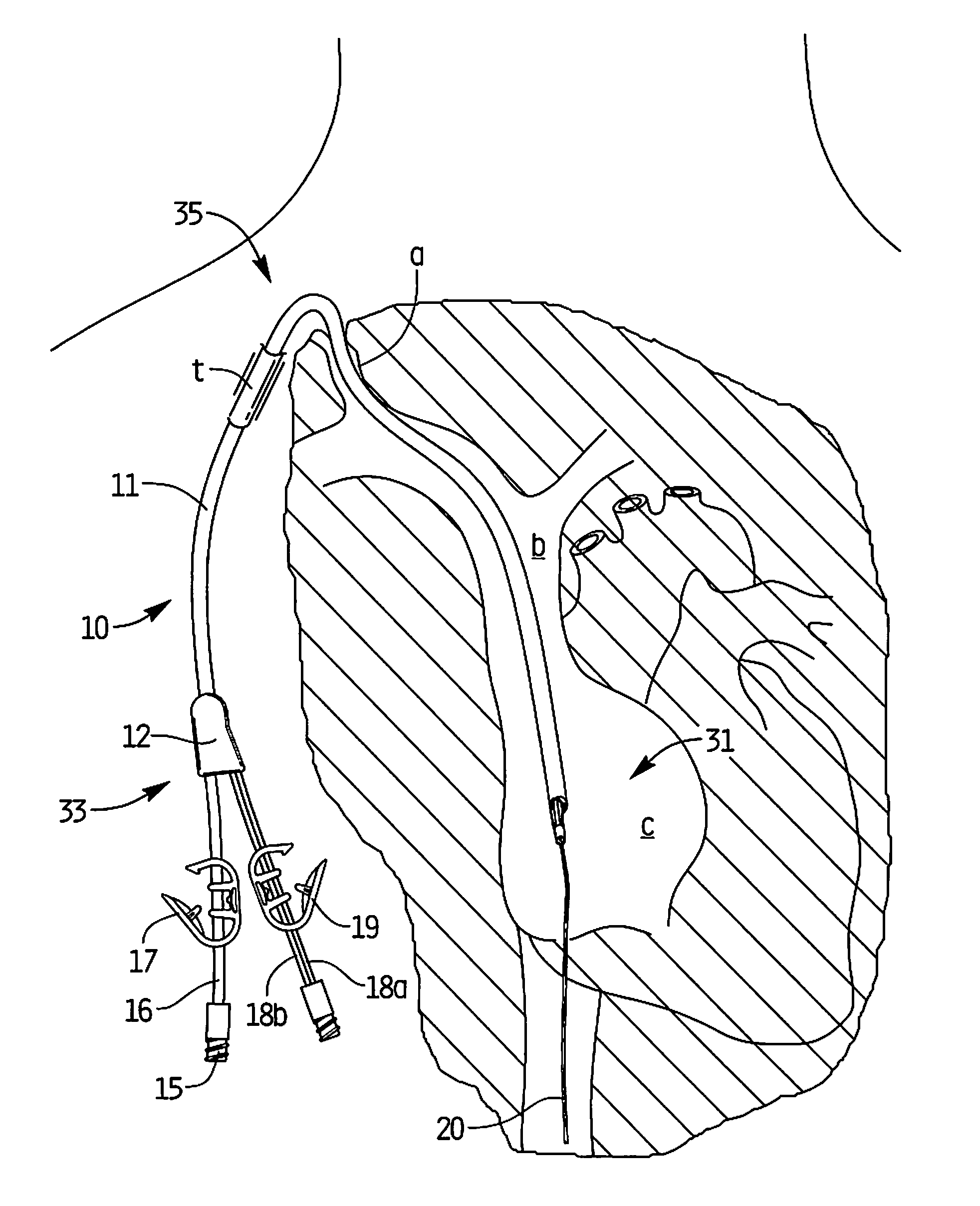
[0041]Referring now in detail to the drawings where like reference numerals identify similar or like components throughout the several views, the catheter of the present invention is designated generally by reference numeral 10. The catheter 10 is typically inserted into an area of high velocity blood flow to ensure sufficient blood can be transported from the body for dialysis. FIG. 5 illustrates the catheter 10 inserted through the right internal jugular vein “a”, into the superior vena cava “b”, and into the right atrium “c”. The catheter 10 can also be inserted for example into the left internal jugular vein, into the superior vena cava “b” and into the right atrium “c”. Insertion into the right atrium, from either the right or left side provides the necessary high blood flow to the dialysis machine. Note that the catheter body (catheter tube) 11 is sufficiently flexible to enable it to bend to accommodate the anatomical curves as shown.

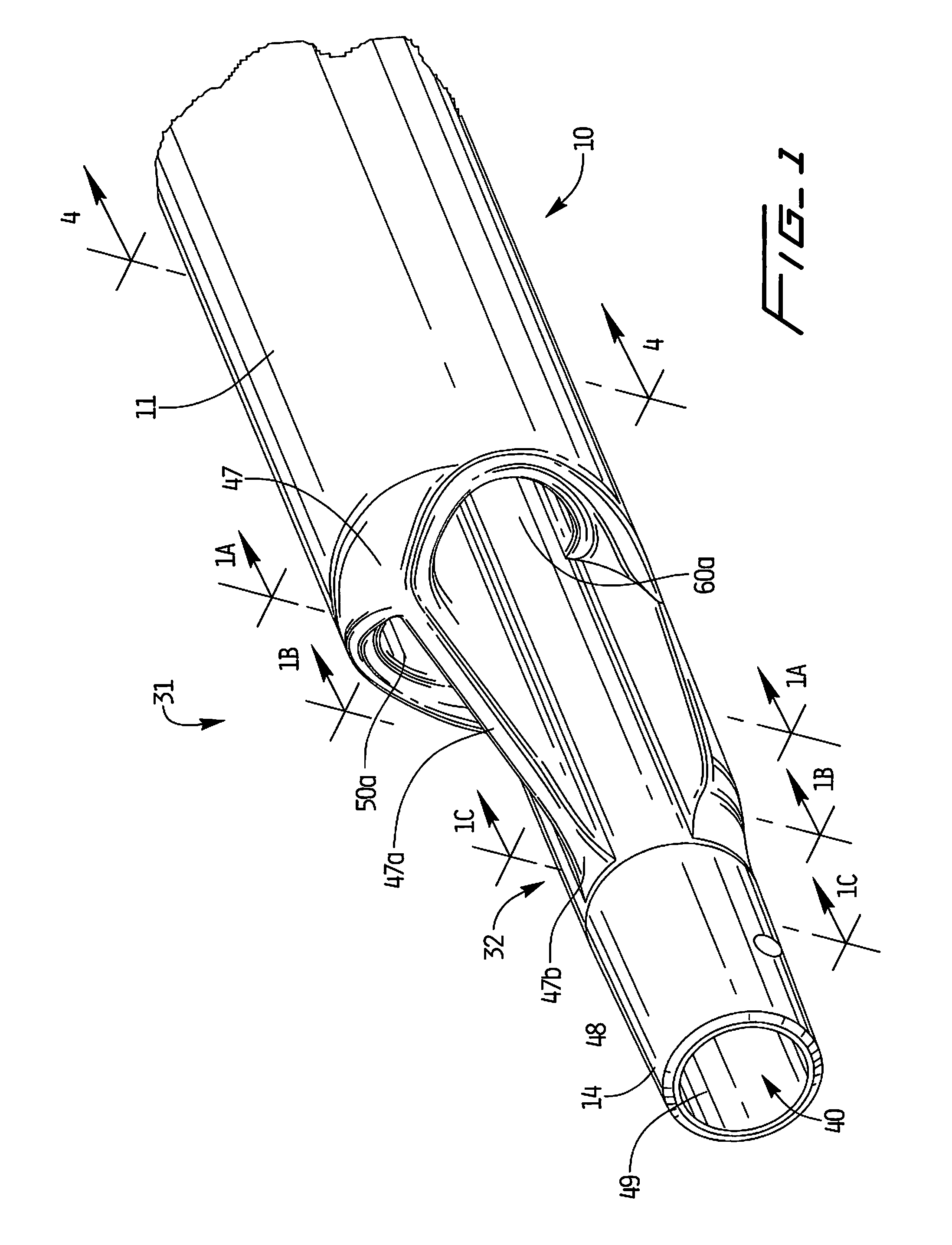
[0042]With reference to FIGS. 1, 3 and 5, ...


PUM


Abstract

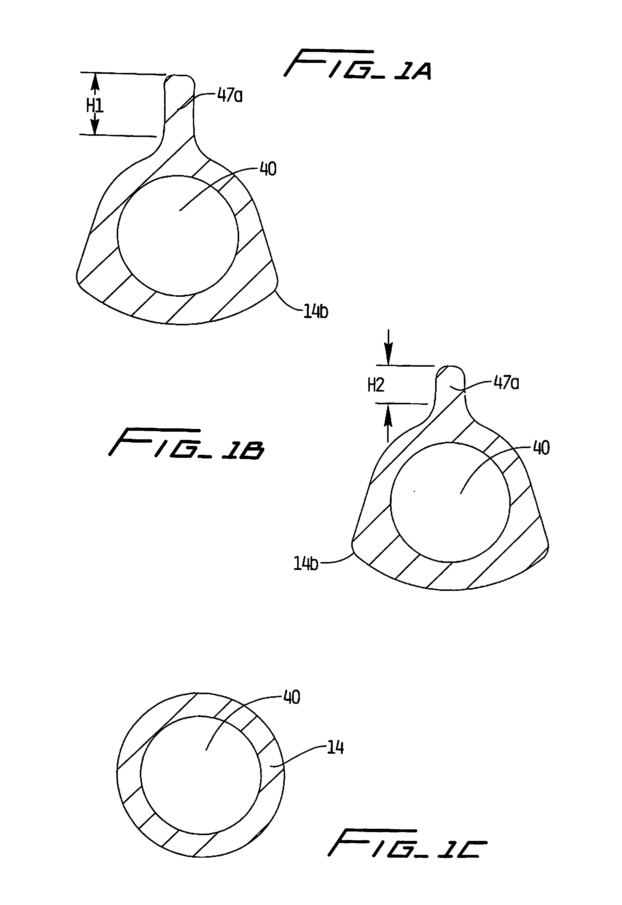
A dialysis catheter including a first portion having an outer wall having a first diameter, an elongated distal portion having a second diameter smaller than the first diameter, and a transition region between the first portion and distal portion. A first longitudinally extending venous lumen is configured to deliver blood. First and second independent longitudinally extending arterial lumens are configured to withdraw blood from a patient. The venous lumen and arterial lumen have first and second regions each positioned a first distance from the outer wall of the catheter and a third region positioned a second shorter distance from the outer wall of the catheter to form an arch shaped wall portion progressively increasing in thickness from the third region toward the first region and from the third region to the second region.

Description

BACKGROUND[0001]This application claims priority from provisional application 61 / 352,195, filed Jun. 7, 2010, the entire contents of which are incorporated herein by reference.TECHNICAL FIELD[0002]This application relates to a catheter and more particularly to a multi-lumen catheter which facilitates hemodialysis.BACKGROUND OF RELATED ART[0003]Hemodialysis is a well known method of providing renal (kidney) function by circulating blood. The kidneys are organs which function to extract water and urea, mineral salts, toxins, and other waste products from the blood with filtering units called nephrons. From the nephrons the collected waste is sent to the bladder for excretion. For patients having one or both defective kidneys, the hemodialysis procedure is life saving because it provides a machine to simulate the function of the kidneys.[0004]In the hemodialysis procedure, blood is withdrawn from the patient's body through a catheter or tube and transported to a dialysis machine, also ...

Claims


Application Information

Patent Timeline
Patent Type & Authority Applications(United States)
IPC IPC(8): A61M1/14
CPCA61M1/3653A61M1/3661A61M25/0026A61M1/3659A61M25/0023A61M25/0032
Inventor DEFONZO, STEPHAN A.
Owner ARGON MEDICAL DEVICES
Learn More