Optical pickup device and optical disc apparatus

a pickup device and optical disc technology, applied in the direction of digital signal error detection/correction, instruments, recording signal processing, etc., can solve the problems of the size of the apparatus, the complexity of the detection optic system, and the cost of the apparatus, so as to achieve the effect of stable servo-signal

Inactive Publication Date: 2011-12-08
HITACHI MEDIA ELECTORONICS CO LTD
View PDF3 Cites 1 Cited by
  • Summary
  • Abstract
  • Description
  • Claims
  • Application Information

AI Technical Summary

Benefits of technology

[0015]According to the present invention, it is possible to provide an optical pickup device for enabling to obtain a stable servo-signal, when recording / reproducing an information recording medium having plural numbers of information recording surfaces, and for enabling small-sizing thereof, and an optical disc apparatus mounting it thereon.

Problems solved by technology

Among of the servo-signals mentioned above, in relation to the tracking error signal, there is a big problem when applying onto a multi-layer disc, which is constructed with two (2) or more of recording layers.
If the signal light and the stray light enter onto the light receiving parts, then two or more light beams interfere with each other, and fluctuating components thereof are detected on the tracking error signal.
For that reason, there is a problem that a detecting optic system comes to be complex and the optical pickup device comes to be large in sizes thereof.
In the Non-Patent Document 1 (Patent Document 2), because of the structures of disposing a photo detector for use of tracking in an outside of the stray light(s) from other layer(s) of the light beam for use of focusing, which is produced on a periphery of the photo detector for use of focusing, and further passing the light diffracting at a central portion of a hologram element into an outside of the stray light(s) from the other layer(s), there is also generated a problem of sizes of the apparatus and a problem of costs thereof, accompanying with large-sizing of the photo detectors.

Method used


Image

  • Optical pickup device and optical disc apparatus
  • Optical pickup device and optical disc apparatus
  • Optical pickup device and optical disc apparatus

Examples


embodiment 1

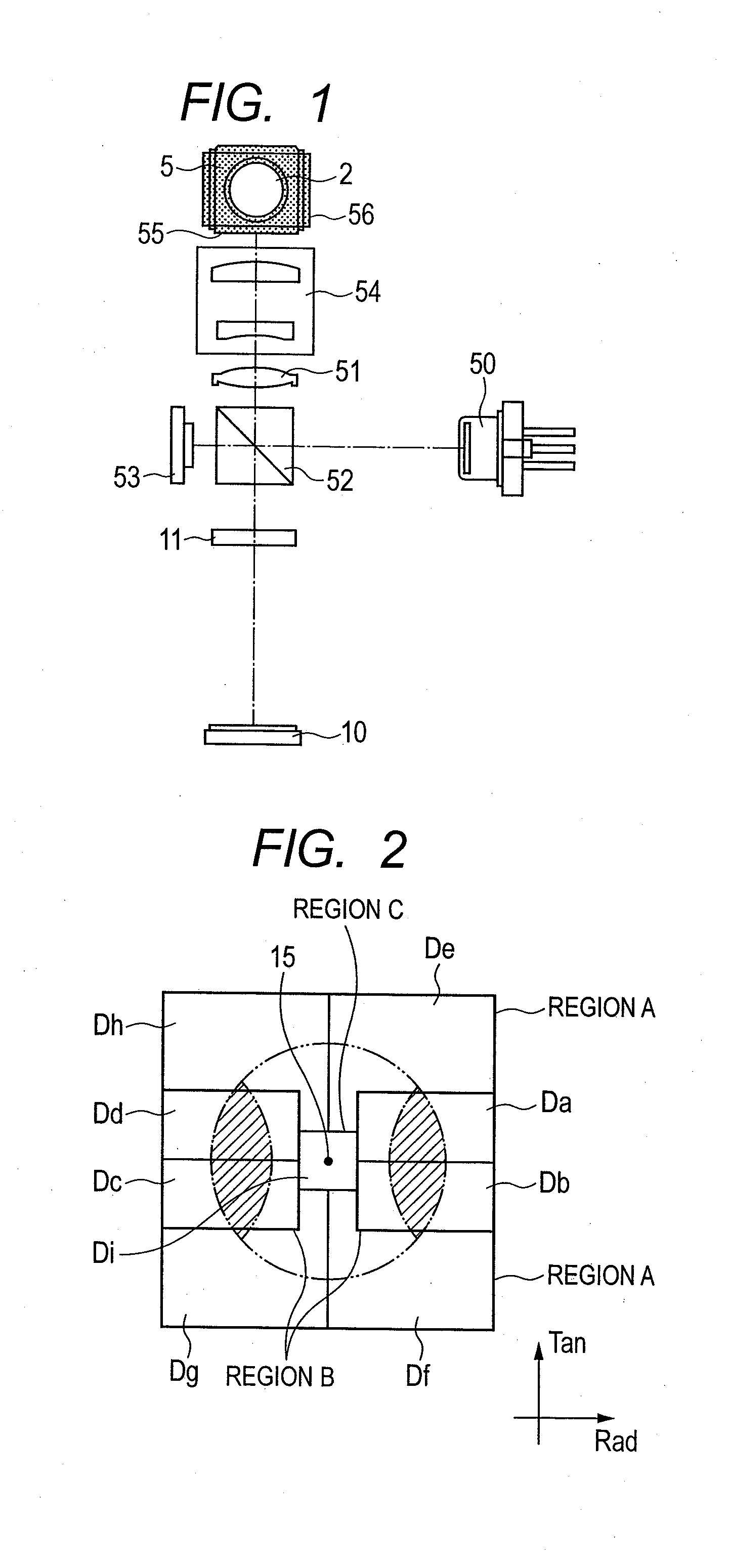
[0032]FIG. 1 shows an optic system of an optical pickup device according to a first embodiment of the present invention. Herein, explanation will be given on a BD (Blu-ray Disc), but may be of other recording method, such as, a DVD (Digital Versatile Disc), etc. However, in the explanation, which will be given below, an optical disc has layers including, such as, a recording layer on a recording-type optical disc and / or a reproducing layer of an optical disc for exclusive use of reproduction.

[0033]From a laser diode 50 is emitted a light beam having a wavelength of about 405 nm, as a divergent light. The light beam emitting from the laser diode 50 is reflected on a beam splitter 52. However, a part of the light beam transmits through the beam splitter 52, and enters into a front monitor 53. In general, when recording information on an optical disc of recording type, such as, a BD-RE, a BD-R, etc., for irradiating a predetermined amount or volume of light upon a recording surface of ...

embodiment 2

[0053]FIG. 8 is a view for showing the light receiving parts of the photo detector 10 of the optical pickup device, according to a second embodiment of the present invention. Difference from the embodiment 1 lies in that the light receiving parts of the photo detector 10 are different from, but other than those are similar to those of the embodiment 1, in the structure thereof.

[0054]From a laser diode 50 is emitted a light beam having a wavelength of about 405 nm, as a divergent light. The light beam emitting from the laser diode 50 is reflected on a beam splitter 52. However, a part of the light beam transmits through the beam splitter 52, and enters into a front monitor 53. In general, when recording information on an optical disc of recording type, such as, a BD-RE, a BD-R, etc., for irradiating a predetermined amount or volume of light upon a recording surface of the optical disc, it is necessary to control the volume of light from the laser diode at high accuracy. For this reas...

embodiment 3

[0065]FIG. 9 is a view for showing the light receiving parts of the photo detector 10 of the optical pickup device, according to a third embodiment of the present invention. Difference from the embodiment 1 lies in that the light receiving parts of the photo detector 10 are different from, but other than those are similar to those of the embodiment 1, in the structure thereof.

[0066]From a laser diode 50 is emitted a light beam having a wavelength of about 405 nm, as a divergent light. The light beam emitting from the laser diode 50 is reflected on a beam splitter 52. However, a part of the light beam transmits through the beam splitter 52, and enters into a front monitor 53. In general, when recording information on an optical disc of recording type, such as, a BD-RE, a BD-R, etc., for irradiating a predetermined amount or volume of light upon a recording surface of the optical disc, it is necessary to control the volume of light from the laser diode at high accuracy. For this reaso...


PUM

PropertyMeasurementUnit
wavelengthaaaaaaaaaa
distanceaaaaaaaaaa
optical phase differenceaaaaaaaaaa

Abstract

In a small-sized optical pickup device for enabling to obtain a stable servo-signal, as well as, a focus error signal and a tracking error signal, without receiving ill influences of stray lights from other layers, when recording / reproducing a multi-layer optical disc, a reflection light from the multi-layer optical disc is divided into plural numbers of regions by a diffraction grating. And, it is divided into at least four (4) regions, by a division line in the tangential direction of the optical disc and a division line in the radial direction thereof. Light receiving parts, for detecting either one of grating diffraction lights, i.e., a +1st dimensional grating diffraction light or a −1st dimensional grating diffraction light of a light beam entering into the at least four (4) regions, are aligned, nearly, on a straight line in the radial direction of the optical disc, and light receiving parts for detecting the other dimensional grating diffraction light are aligned, shifting, with respect to a direction nearly coincident with a tangential direction of the optical disc.

Description

[0001]This application relates to and claims priority from Japanese Patent Application No. 2010-129530 filed on Jane 7, 2010, the entire disclosure of which is incorporated herein by reference.BACKGROUND OF THE INVENTION[0002]The present invention relates to an optical pickup device and also an optical disc apparatus.[0003]As the background art of a field of the present technology is already known Japanese Patent Laying-Open No. 2006-344344 (Patent Document 1). In this Patent Document 1 is described, as the problem to be dissolved, “Obtaining a desired signal from an optical disc having plural numbers of recording layers, at high accuracy”, and as the means for dissolving, there is described, “A light flux of P-polarization emitting from a light source unit 51 is reflected on a optical disc 15, and enters into a lens 61 while becoming the S-polarization light. And, on quarter wave plates 62 and 63, each is given with an optical phase difference of +¼ wavelength to the light flux ent...

Claims


Application Information

Patent Timeline
Patent Type & Authority Applications(United States)
IPC IPC(8): G11B7/135G11B7/095
CPCG11B7/0901G11B7/0908G11B2007/0013G11B7/1353G11B7/131
Inventor YAMAZAKI, KAZUYOSHITOMITA, DAISUKE
Owner HITACHI MEDIA ELECTORONICS CO LTD
Why Eureka
Try Eureka