
Motion Sensor, Method, and Computer-Readable Storage Medium Providing a Motion Sensor That Can Rapidly Calibrate Gains

a motion sensor and gain calibration technology, applied in the direction of electrical/magnetically converting sensor output, linear/angular speed measurement, instruments, etc., can solve the problems of small time available for calibration, proximity detector primarily tends to experience rotational vibration, and primarily experiences translational vibration. , to achieve the effect of more accurate gain calibration and rapid gain calibration

Active Publication Date: 2011-12-08
ALLEGRO MICROSYSTEMS INC
View PDF2 Cites 77 Cited by
  • Summary
  • Abstract
  • Description
  • Claims
  • Application Information

AI Technical Summary

Benefits of technology

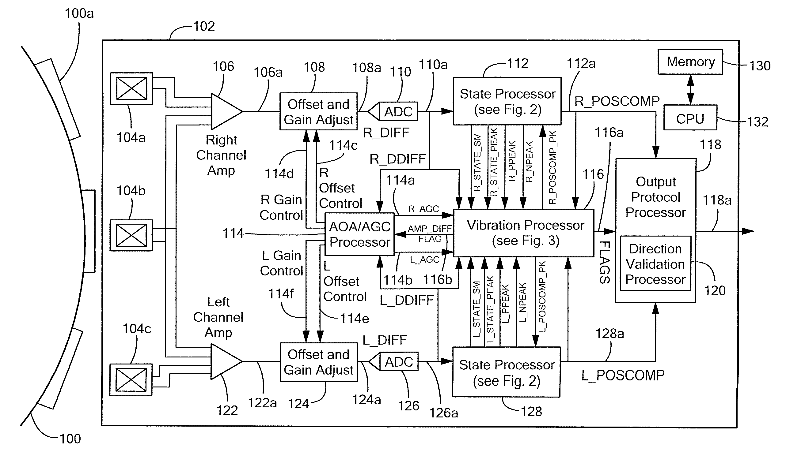
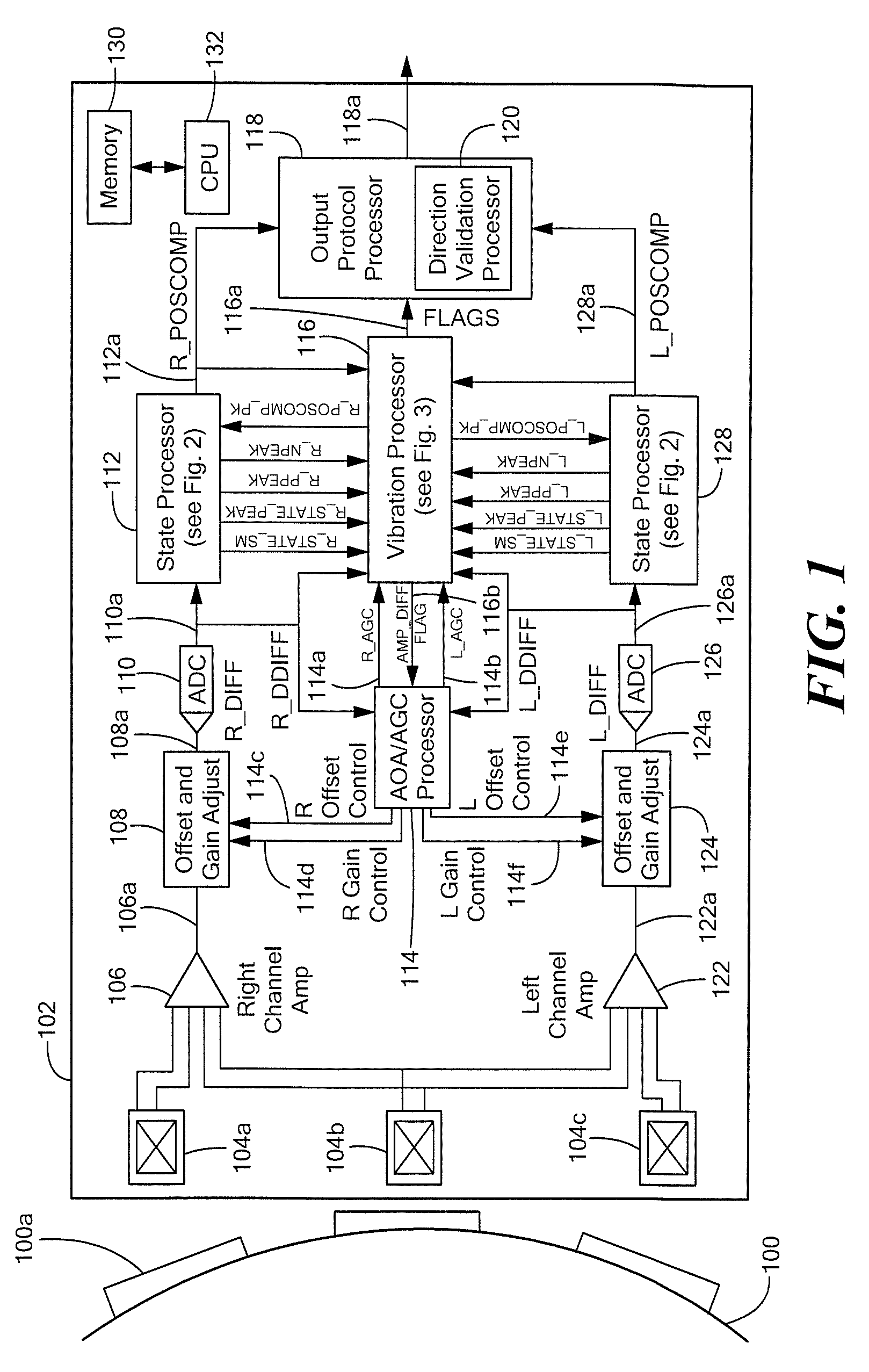
[0023]The motion sensor, method, and computer-readable medium of the claimed invention provide a motion sensor that has improved edge placement (or other representation of rotational angle) in an output signal generated by the motion sensor. The motion sensor will provide directional information in the output signal once it is deemed to be accurate. The motion sensor will rapidly and accurately calibrate.
[0027]With the above arrangements, a motion sensor can provide more accurate gain calibration of two channels of the motion sensor, even when experiencing a vibration. The motion sensor can also achieve a more rapid gain calibration.

Problems solved by technology

For example, when used in an automobile transmission, during starting of the automobile engine, the proximity detector primarily tends to experience rotational vibration, which tends to generate magnetic field signals having a first wave shape.
In contrast, during engine idle, the proximity detector primarily tends to experience translational vibration, which tends to generate magnetic field signals having a second wave shape.
Thus, for fast magnetic field signals (e.g., for fast rotating gears), the time available for calibration is small.
In those applications for which the movement or rotation is rapid and the time available for calibration is small, the rotation detector might not calibrate properly, i.e., the threshold might not be properly determined.
It may be adverse to the operation of a system, for example, an automobile system in which the proximity detector is used, for the system to interpret an output signal from the proximity detector to be associated with a rotation in normal operation when only a vibration is present.
Therefore, the antilock brake system might not operate as intended.
It may also be undesirable to perform a proximity detector calibration in response to a vibration rather than in response to a rotation in normal operation.
Since the conventional proximity detector cannot distinguish a magnetic field signal generated in response to a rotation in normal operation from a magnetic field signal generated in response to a vibration, the proximity detector may perform calibrations at undesirable times when experiencing the vibration, and therefore, result in inaccurate calibration.
Due to noise (electrical or vibrational) the motion sensor may not accurately position edges of an output signal, which edge placements are representative of an absolute number of degrees of rotation of the sensed object.
Also due to such noise, the motion sensor may generate an inaccurate output signal, particularly near to a time of power up when vibrations are highest, that has edges that are inaccurately placed.

Method used


Image

  • Motion Sensor, Method, and Computer-Readable Storage Medium Providing a Motion Sensor That Can Rapidly Calibrate Gains
  • Motion Sensor, Method, and Computer-Readable Storage Medium Providing a Motion Sensor That Can Rapidly Calibrate Gains
  • Motion Sensor, Method, and Computer-Readable Storage Medium Providing a Motion Sensor That Can Rapidly Calibrate Gains

Examples


Embodiment Construction

[0053]Before describing the present invention, some introductory concepts and terminology are explained. As used herein, the term “magnetic field sensing element” is used to describe a variety of types of electronic elements that can sense a magnetic field. The magnetic field sensing elements can be, but are not limited to, Hall effect elements, magnetoresistance elements, or magnetotransistors. As is known, there are different types of Hall effect elements, for example, planar Hall elements, vertical Hall elements, circular Hall elements. As is also known, there are different types of magnetoresistance elements, for example, anisotropic magnetoresistance (AMR) elements, giant magnetoresistance (GMR) elements, tunneling magnetoresistance (TMR) elements, Indium antimonide (InSb) elements, and magnetic tunnel junction (MTJ) elements.

[0054]As is known, some of the above-described magnetic field sensing elements tend to have an axis of maximum sensitivity parallel to a substrate that su...


PUM


Abstract

A motion sensor has a channel amplitude difference processor configured to adjust gains of two channels to bring a gain of a one channel toward a gain of the other channel when a gain mismatch is detected.

Description

CROSS REFERENCE TO RELATED APPLICATIONS[0001]Not Applicable.STATEMENT REGARDING FEDERALLY SPONSORED RESEARCH[0002]Not Applicable.FIELD OF THE INVENTION[0003]This invention relates to motion sensors, and more particularly, to a motion sensor that has a channel amplitude difference processor to rapidly calibrate gains.BACKGROUND OF THE INVENTION[0004]Magnetic field sensors (e.g., rotation detectors) for detecting ferromagnetic articles and / or magnetic articles are known. The magnetic field associated with the ferromagnetic article or magnetic article is detected by a magnetic field sensing element, such as a Hall element or a magnetoresistance element, which provides a signal (i.e., a magnetic field signal) proportional to a detected magnetic field. In some arrangements, the magnetic field signal is an electrical signal.[0005]The magnetic field sensor processes the magnetic field signal to generate an output signal that, in some arrangements, changes state each time the magnetic field...

Claims


Application Information

Patent Timeline
Patent Type & Authority Applications(United States)
IPC IPC(8): G01B7/00
CPCG01D5/145G01D5/2448G01P3/487G01D5/14G01P3/489G01P21/00G01P3/488
Inventor FOLETTO, ANDREAFERNANDEZ, DEVONBURDETT, ERIC
Owner ALLEGRO MICROSYSTEMS INC
Learn More