Throttle Valve
a technology of valves and valve bodies, applied in the direction of valve operating means/releasing devices, light and heating equipment, refrigeration components, etc., can solve the problems of high cost of current electronic expansion valves for refrigerant flow regulating, excessive components in the transmission mechanism, complex structure and high weight, etc., to achieve simple structure, simple structure, and light weight
- Summary
- Abstract
- Description
- Claims
- Application Information
AI Technical Summary
Benefits of technology
Problems solved by technology
Method used
Image
Examples
first embodiment
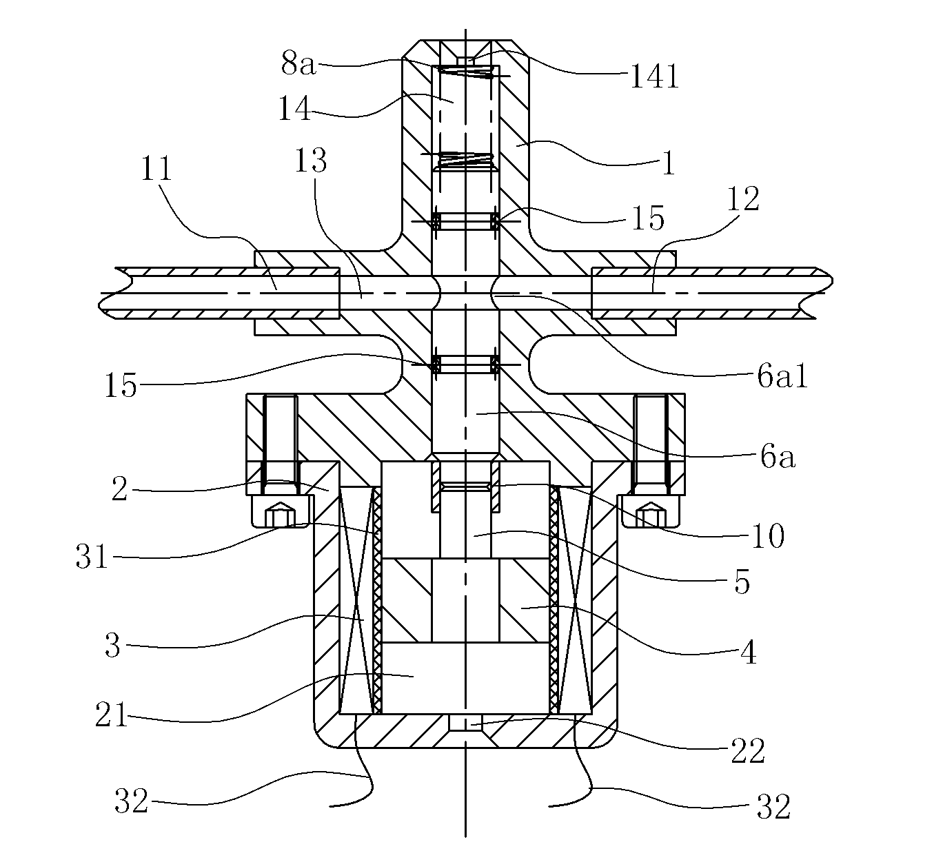
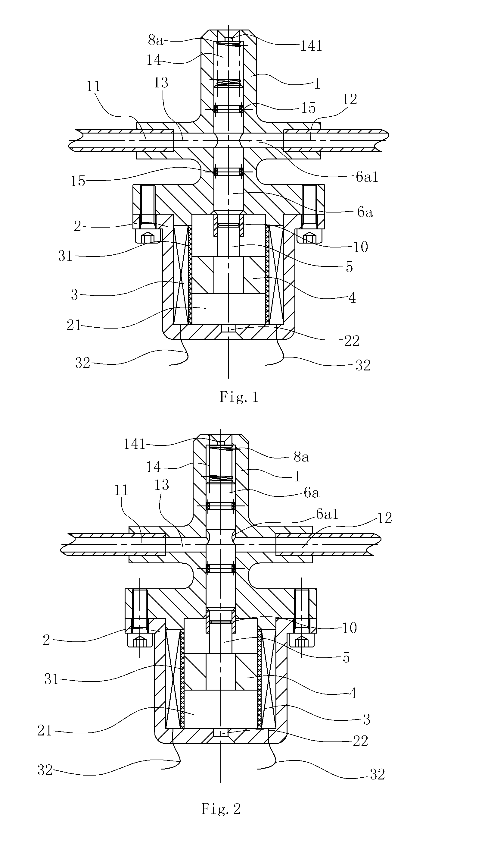
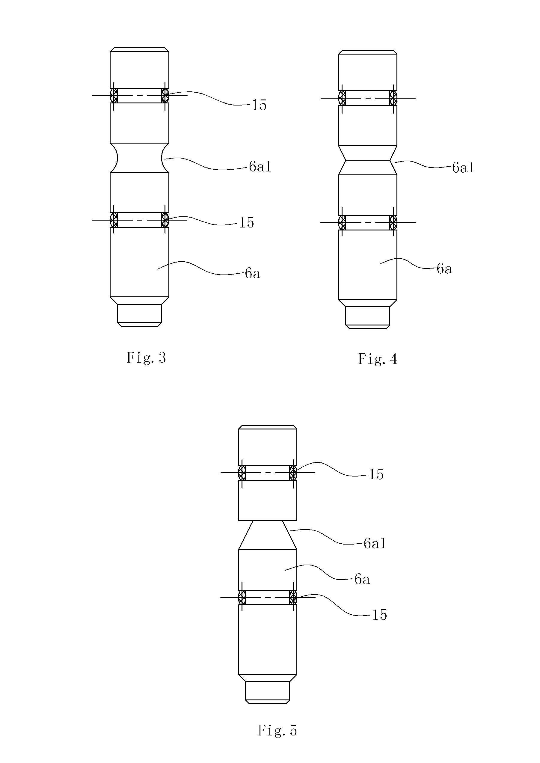
[0044]FIGS. 1˜5 show the present invention.
[0045]In this embodiment, the throttle valve comprises a valve body 1, a valve core and a driving mechanism for the valve core.
[0046]The valve body 1 is provided with an inlet 11 and an outlet 12 on the wall of the valve body 1 which are both on the same horizontal axis. A flow passage 13 with a linear axis is disposed in the valve body 1 which communicated with the inlet 11 and the outlet 12, and a mounting hole 14 is disposed in the valve body 1 which communicated with the flow passage 13, the mounting hole 14 runs across the flow passage 13 in this embodiment.
[0047]In this embodiment, the valve core is a plunger piston 6a which is movably inserted inside the mounting hole 14 and is able to slide relatively to the valve body 1. An upper portion of the plunger piston 6a is located in a portion of the mounting hole 14 which is above the flow passage 13; a seal ring 15 is disposed between the peripheral wall of upper portion of the plunger p...
second embodiment
[0060]FIG. 6 and FIG. 7 show the present invention.
[0061]The difference of this embodiment compared with the first embodiment is that, a liner tube 9 is tightly inserted into the mounting hole 14, the liner tube 9 has a through hole 91 which is communicated with the flow passage 13, the through hole 91 is located in the flow passage 13 and the section of the flow passage 13 fully covers the section of the through hole 91, while the plunger piston 6a is located in the liner tube 9; seal rings 15 are respectively disposed between the peripheral wall of upper portion of the plunger piston 6a and the inner wall of the liner tube 9, and between the peripheral wall of lower portion of the plunger piston 6a and the inner wall of the liner tube 9.
[0062]The liner tube 9 can be made of good wear-resistant materials such as wear-resistant steels, therefore, the plunger piston 6a will not directly rub the inner wall of the mounting hole 14 and will directly rub the inner wall of the liner tube ...
third embodiment
[0063]FIG. 8 and FIG. 9 show the present invention.
[0064]The difference of this embodiment compared with the first embodiment is that, although the elastic part is a spring 8a which locates in the cavity 21 of the valve seat 2, and one end of the spring 8a resist against the bottom of the magnetic element 4.
[0065]In this embodiment, the current direction of the coil 3 is opposite to that of the first embodiment, that is, the electromagnetic force of the coil 3 on the magnetic element 4 is downward and opposite to that of the first embodiment.
[0066]FIG. 10 and FIG. 11 show the forth embodiment of the present invention.
[0067]The difference of this embodiment compared with the third embodiment is that, a liner tube 9 is tightly inserted into the mounting hole 14, the liner tube 9 has a through hole 91 which is communicated with the flow passage 13, the through hole 91 is located in the flow passage 13 and the section of the flow passage 13 fully covers the section of the through hole 9...
PUM
 Abstract
Description
Claims
Application Information
 - R&D
- Intellectual Property
- Life Sciences
- Materials
- Tech Scout
- Unparalleled Data Quality
- Higher Quality Content
- 60% Fewer Hallucinations
Browse by: Latest US Patents, China's latest patents, Technical Efficacy Thesaurus, Application Domain, Technology Topic, Popular Technical Reports.
© 2025 PatSnap. All rights reserved.Legal|Privacy policy|Modern Slavery Act Transparency Statement|Sitemap|About US| Contact US: help@patsnap.com


