Cup holder

Active Publication Date: 2011-12-08
HONDA MOTOR CO LTD +2
View PDF20 Cites 13 Cited by
  • Summary
  • Abstract
  • Description
  • Claims
  • Application Information

AI Technical Summary

Benefits of technology

[0010]According to the above aspect of the present invention described in (1) above, when a container of a beverage is pulled out from the storing part and the storing part became stuck at a constricted part of the container of the beverage, and when a user pushes in the holder in order to release the storing part being stuck, the holder pushed into the opening part of the storing part is restricted by a restricting part from moving in a direction in which the holder is pushed in. Therefore, the load being applied to the axial part is reduced. Further, the axial part is prevented from breaking. Further, it is not necessary to enlarge the axial part in order to enhance the robustness of the axial part. Neither is it necessary to enlarge other periphery components. Therefore, the size may be made smaller and the weight may be made lighter.
[0012]According to the above aspect of the present invention described in (3) above, the restricting part may operate as a reinforcing component to enhance the robustness of the opening part. Thus, it is not necessary to increase the thickness around the opening part. Neither is it necessary to provide a separate reinforcing component. In this way, the size may be made smaller.
[0013]According to the above aspect of the present invention described in (4) above, even when the holder becomes stuck at a constricted part of a container of a beverage when the container of the beverage is pulled up, a force, being applied from the container of the beverage to the holder due to the pulling force of the container of the beverage, is applied so as to push in the holder. Therefore, the pulling up of the container of the beverage may be tolerated. Even if the user feels that the container of the beverage cannot be pulled up, and inserts a finger between the container of the beverage and the storing part and pushes in the holder, the restricting part allows the user to feel that the holder has been pushed into a releasing position. In this way, the restricting part prevents a movement pushing the holder any further.

Problems solved by technology

Further, when there is a constricted part at an outer peripheral surface of the container of the beverage, the holder might become stuck in the constricted part of the container of the beverage that is about to be removed.

Method used


Image

  • Cup holder
  • Cup holder
  • Cup holder

Examples


Embodiment Construction

[0021]Hereunder, an embodiment of the present invention is described with reference to the diagrams. In the following description and diagrams, FR indicates a frontal side of a vehicle.

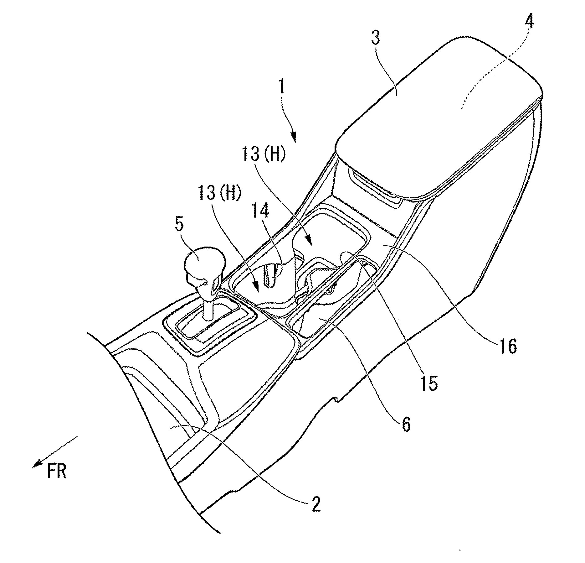
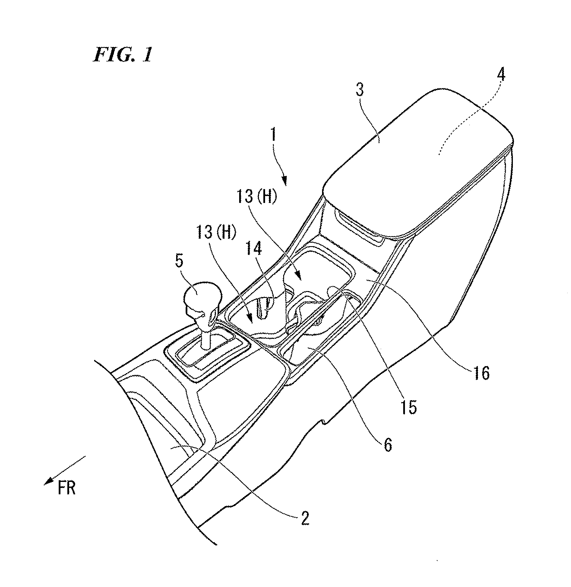
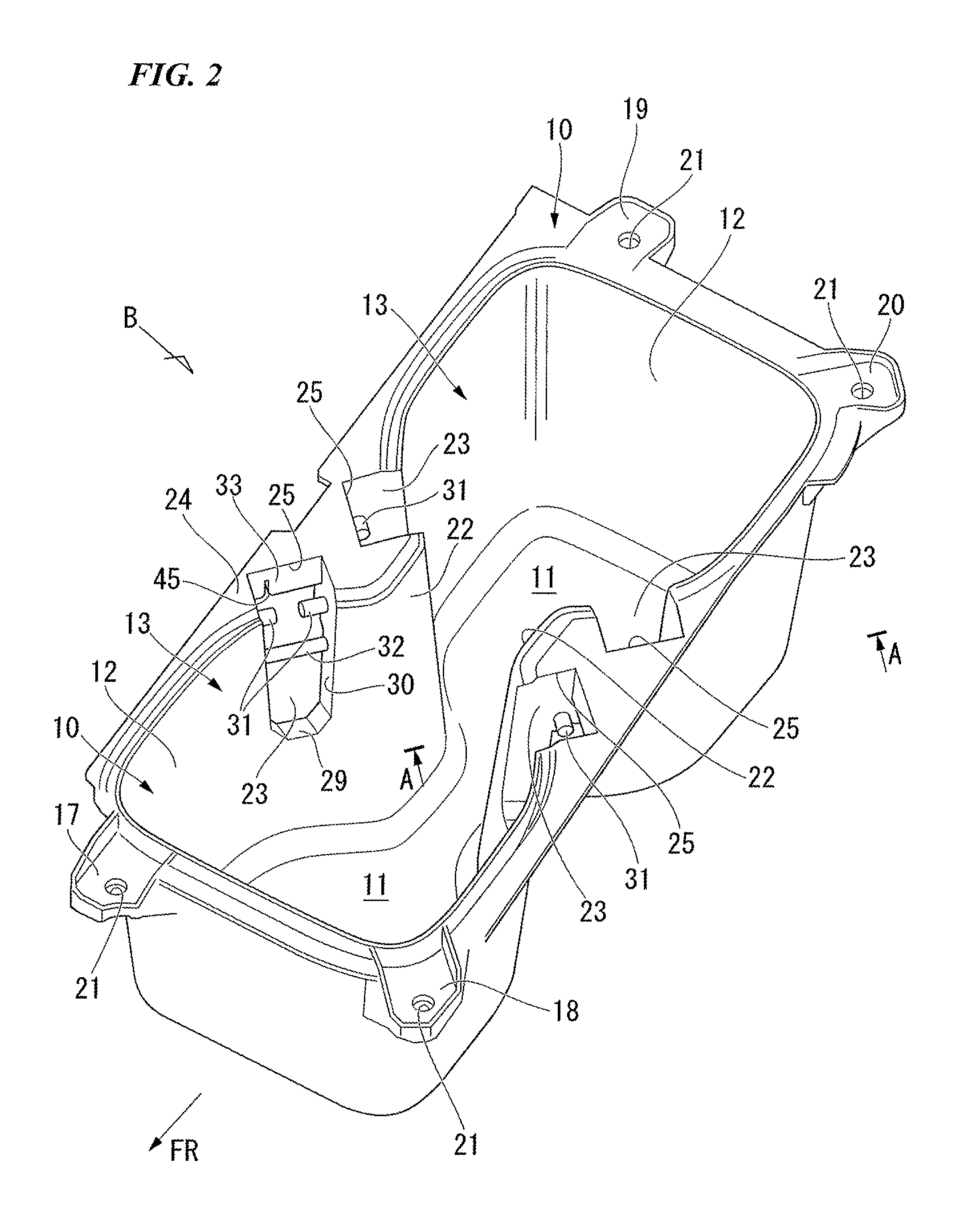
[0022]In FIG. 1, element 1 indicates a console 1 placed between a driver's seat of a vehicle and a passenger's seat. A front portion storing part 2 is provided at a front portion of the console 1 in a front-rear direction of the vehicle. An upper portion of the front portion storing part 2 is opened. A rear portion storing part 4 is provided at a rear portion of the console 1. The rear portion storing part 4 is covered by a lid 3 which may be opened and closed. An upper portion of the lid 3 acts as an arm rest. An AT lever 5 is placed at a rear portion of the front portion storing part 2. Two cup holders H, H are placed between the position of the AT lever 5 and the rear portion storing part 4. The cup holders H, H are placed along the front-rear direction of the vehicle. Incidentally, a lever opening...


PUM


Abstract

A cup holder holding an object includes: a storing part being cylindrical and being opened at an upper portion; an opening part provided at a side wall of the storing part; a holder being biased towards an interior of the storing part and being stored inside the opening part so that the holder may protrude and retract; and a restricting part provided on the opening part, wherein the restricting part restrains a movement of the holder at a maximum storage position.

Description

[0001]The present application claims priority on Japanese Patent Application No. 2010-129226, filed Jun. 4, 2010, the content of which is incorporated herein by reference.BACKGROUND OF THE INVENTION[0002]1. Field of the Invention[0003]The present invention relates to a cup holder of a vehicle, for example. A container of a beverage may be placed on the cup holder. In particular, the present invention relates to a cup holder which supports a peripheral wall of the container of the beverage that is placed, thereby preventing the container of the beverage from wobbling.[0004]2. Description of the Related Art[0005]Conventional cup holders have been configured as follows: First, the cup holder comprises a storing part of a container of a beverage, which is opened in an upward direction. An opening part is provided at an upper portion of a side wall of this storing part. A pivot shaft is provided on this opening part. An axis of the pivot shaft is in a horizontal direction. A support is m...

Claims


Application Information

Patent Timeline
IPC IPC(8): B60R7/04
CPCB60N3/101B60R7/04B60N3/106
Inventor KAMIYA, TAKUKINOU, HIROYUKIOGAWA, ATUSHIUEHARA, TAKUYA
Owner HONDA MOTOR CO LTD
Why Eureka
Try Eureka