Flexible material for surface adhesive rule

a flexible material and adhesive rule technology, applied in the field of diecutting/creasing industry, can solve the problems of cardboard prone to get stuck in steel rules, and achieve the effects of reducing the number and severity of ply cracks, improving the quality of the surface of pre-treated cardboard creases, and reducing the number of ply cracks

Inactive Publication Date: 2011-12-01
HIGHCON SYST
View PDF5 Cites 29 Cited by
  • Summary
  • Abstract
  • Description
  • Claims
  • Application Information

AI Technical Summary

Benefits of technology

[0025]The novel surface-adhesive-rule technology (SART) enables the manufacture of a complete surface-adhesive-rule die with the creation of its surface-adhesive rules (SAR) by one machine. Thus, advantageously, utilizing the SART alleviates the requirement for complex operation between different companies. Furthermore, another advantage of the surface-adhesive-rule technology (SART) is that it may be fully automatic and controlled by a computer, for example. Thus, no skilled craftsmen (specialists) are required in the manufacturing of a die. In addition, the surface-adhesive-rule technology (SART) alleviates the need for warehouse space because the layout and all information related to the surface-adhesive-rule die may be stored on a computer or other storing medium such as CDROM, flash disc, etc. Thus the novel surface-adhesive-rule technology (SART) advantageously provides a low-cost, easy to use, friendly to the environment, and a shortened lead-time for production of a full surface-adhesive-rule die and counter die.
[0062]The nozzle of the drawing-head may have one or more orifices. The orifice may determine the surface-adhesive rule profile / shape or may be selected to obtain a desired profile / shape. The orifice may be located at the bottom of the nozzle, at the side of the nozzle, on an edge of the nozzle, or a combination of multiple placements, etc. In exemplary embodiments, the nozzle may be quickly and easily disassembled or detached from the drawing-head and a different nozzle may be assembled or attached to the drawing-head. The inside of the nozzle and / or orifice may have a coating that operates to reject or repel the flexible material. Advantageously, this characteristic helps to prevent clogging or blockage, either partial or complete, of the orifice. The shape and placement of the orifice may be determined according to different criteria. Exemplary criteria may include, but is not limited to: adhesive requirements of the SAR to the surface of the SARD's body; the drawing-termination technique used; the required surface-adhesive rule profile; and so on.

Problems solved by technology

Without the ejection rubber the cardboard may tend to get stuck amongst the steel rules.

Method used


Image

  • Flexible material for surface adhesive rule
  • Flexible material for surface adhesive rule
  • Flexible material for surface adhesive rule

Examples


Embodiment Construction

[0106]Turning now to the figures in which like numerals and / or labels represent like elements throughout the several views, exemplary embodiments of the present disclosure are described. For convenience, only some elements of the same group may be labeled with numerals. The purpose of the drawings is to describe exemplary embodiments and is not for production purpose. Therefore features shown in the figures are for illustration purposes only and are not necessarily drawn to-scale and were chosen only for convenience and clarity of presentation.

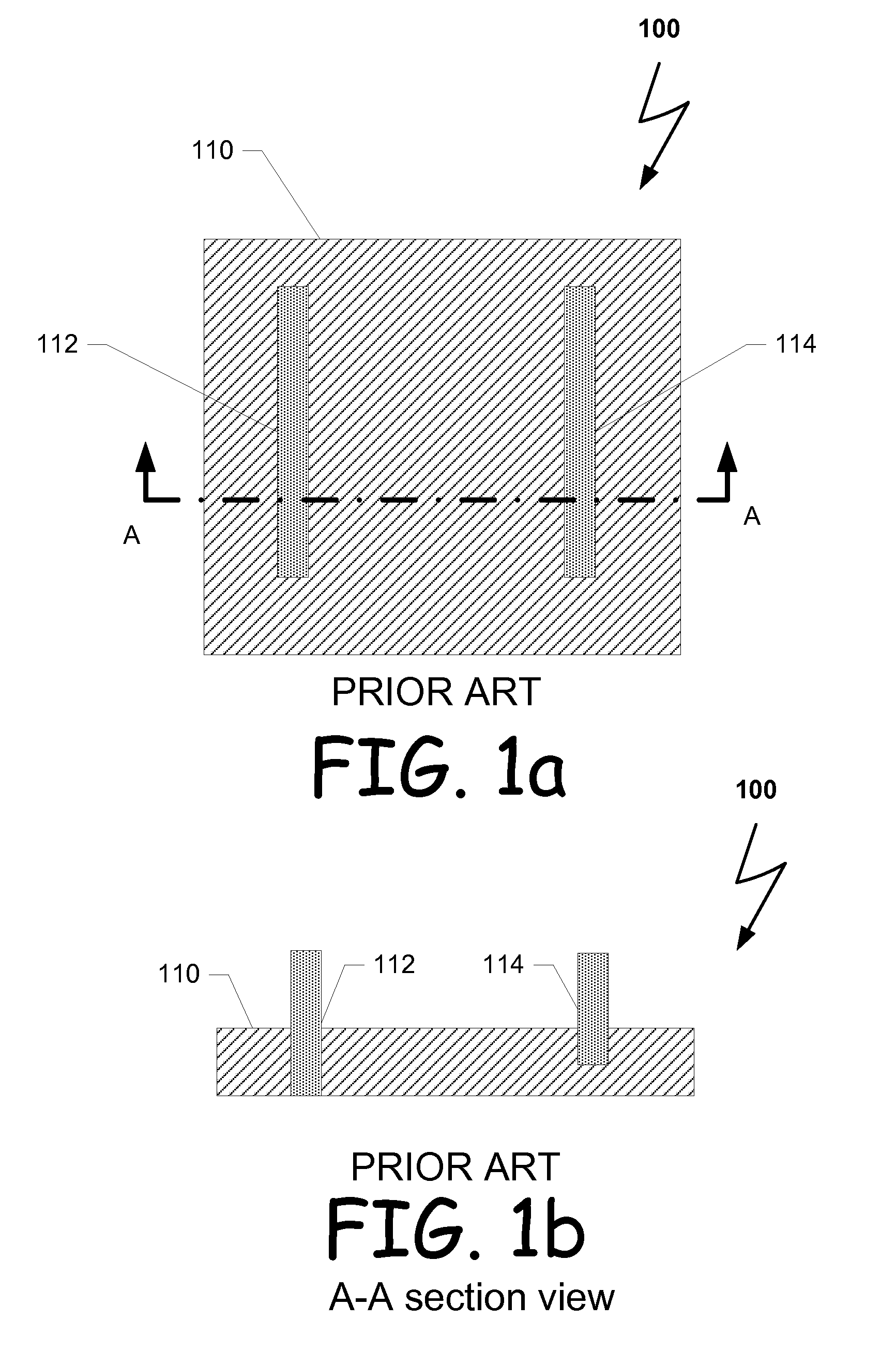
[0107]FIG. 1a depicts a block diagram with relevant elements of an exemplary common prior art steel-rule die 100. Steel-rule die 100 may comprise a body 110, and a plurality of steel-rules: steel-rule 112 and steel-rule 114, for example. Steel-rules 112 and 114 may be cutting rules, creasing rules, embossing rules, etc. The body 110 may be made of hard-wood material, for example.

[0108]FIG. 1b depicts cross-sectional view of the exemplary prior...


PUM

PropertyMeasurementUnit
Fractionaaaaaaaaaa
Fractionaaaaaaaaaa
Fractionaaaaaaaaaa

Abstract

A flexible material that comprises one or more types of polymers and may be used for drawing surface-adhesive rules having a pre-defined cross-section profile. Wherein the flexible material has attribute to reserve a shape of a profile of an orifice through which it is deposited from.

Description

CROSS-REFERENCE TO RELATED APPLICATIONS[0001]This is a utility patent application being filed in the United States as a non-provisional application for patent under Title 35 U.S.C. §100 et seq. and 37 C.F.R. §1.53(b) and, claiming the benefit of the prior filing date under Title 35, U.S.C. §119(e) of the United States provisional application for patent that was filed on May 17, 2010 and assigned Ser. No. 61 / 345,180, which application is incorporated herein by reference in its entirety. This application is related to and filed concurrently with: U.S. application Ser. No. ______ bearing the title of METHOD AND SYSTEM FOR SURFACE ADHESIVE RULE TECHNOLOGY, filed on May 16, 2011 under the attorney docket number 08025.1030; U.S. application Ser. No. ______ bearing the title of METHOD AND SYSTEM FOR CREATING CO-LAYER SURFACE ADHESIVE RULE, filed on May 16, 2011 under the attorney docket number 08025.1040; and U.S. application Ser. No. ______ bearing the title of METHOD AND SYSTEM FOR CREAT...

Claims


Application Information

Patent Timeline
IPC IPC(8): C08L23/12C08F110/06C08G63/00C08G69/08C08K5/541C08L75/04C08L67/00C08L77/00C08L69/00C08K3/36C08G18/32C08G64/00B31B50/20
CPCC08L23/02C08L23/16C08L77/00B31B1/20C08G2280/00C08L75/04C08L83/04
Inventor ZIMMER, MICHAELRATZMAN, AVIVIDAN, DAVIDDAHAN, LIORSPIRYAGIN, KOSTANTIN
Owner HIGHCON SYST
Why Eureka
Try Eureka