Heat Dissipation Module

a heat dissipation module and heat dissipation technology, applied in the direction of lighting and heating apparatus, basic electric elements, semiconductor devices, etc., can solve the problems of high heat dissipation density, high temperature of electronic parts, and high heat generation of electronic parts, so as to achieve thin and lighter

Inactive Publication Date: 2011-12-01
ASIA VITAL COMPONENTS SHENZHEN CO LTD
View PDF52 Cites 3 Cited by
  • Summary
  • Abstract
  • Description
  • Claims
  • Application Information

AI Technical Summary

Benefits of technology

[0012]In order to overcome the deficiencies of the preceding prior art, an object of the present invention is to provide a heat dissipation module which is thinner and lighter. According to the present invention, the heat dissipating module includes a cooling base, a heat dissipating component, and at least one heat pipe. The cooling base includes a heating surface and a conducting surface. On the heating surface is disposed at least one joining part to hold and connect the heat pipe. which includes a heat absorbing end and a heat dissipating end. The heat absorbing end of the heat pipe is disposed on the joining part of the cooling base. A flat surface parallel to the heating surface of the cooling base is formed on the heat absorbing end.

Problems solved by technology

But under working condition these electronic parts often generate a great amount of heat and have high heating density.
This causes the temperatures of the electronic parts to rise speedily.
Without proper heat dissipation, the electronic parts will be overheated and their performance destabilized; the whole electronic devices may consequently stop functioning, crash, or even burn.
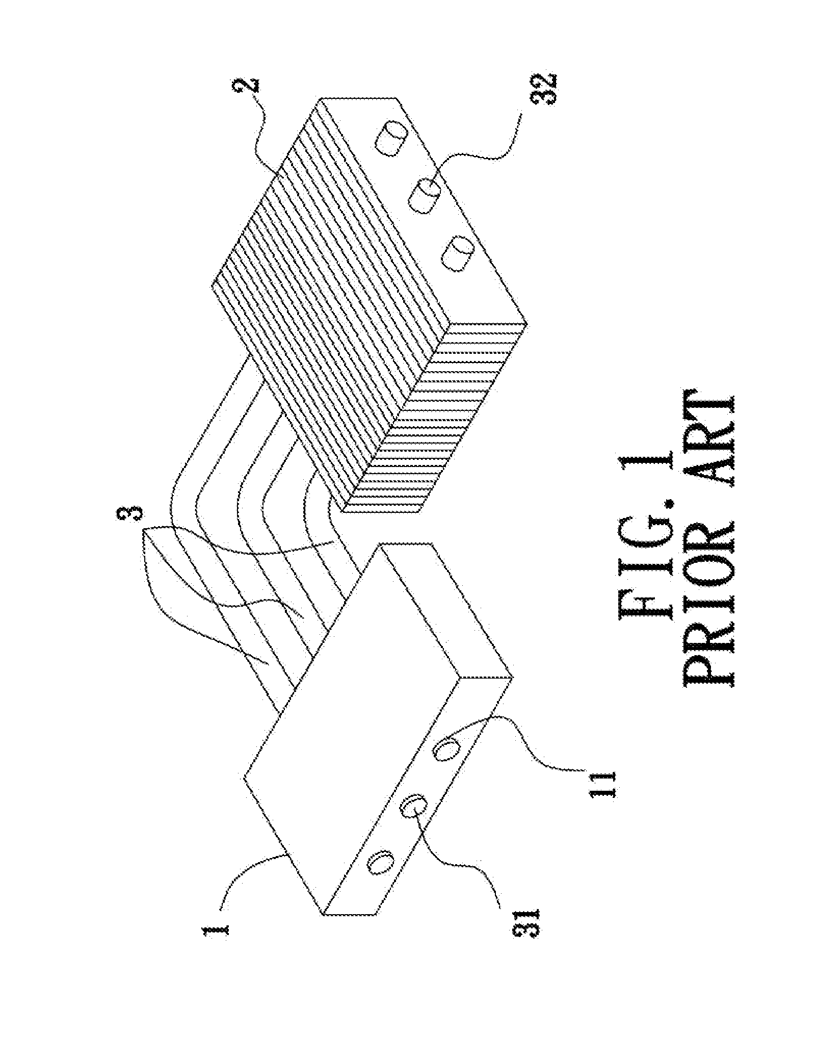
Although the conventional heat dissipation module is efficient in dissipating heat, it has one deficiency in manufacturing.
The cooling base 1 of the conventional heat dissipation module is therefore thick, heavy, and costly to make.
1. It is costly to make;

Method used


Image

  • Heat Dissipation Module
  • Heat Dissipation Module
  • Heat Dissipation Module

Examples


Embodiment Construction

[0017]The foregoing object, structure, and function of the present invention are hereinafter described with reference to its preferred embodiment as shown in FIGS. 3 and 4.

[0018]Referring to FIGS. 3 and 4, a heat dissipation module according to the preferred embodiment of the present invention includes a cooling base 20 and at least one heat pipe 30. The cooling base 20 includes a heating surface 201 and a conducting surface 202 on the opposite side thereof. On the cooling base 20 is disposed at least one joining part 203, which can be in the form of a slot. At least one side thereof is designed as a flat surface 204. The said heating surface 201 is tightly attached to a heating component C (for example a CPU) to dissipate the heat generated by the said heating component C by absorbing and conducting it to heat pipe 30.

[0019]The said heat pipe 30 includes a heat dissipating end 310 and a heat absorbing end 320 thereon at least one flat surface 321 is formed. The said flat surface 32...


PUM


Abstract

A heat dissipation module includes a cooling base, a heat dissipating component, and at least one heat pipe. The cooling base includes a heating surface and a conducting surface. On the heating surface is disposed at least one joining part to hold and connect the heat pipe. The heat pipe includes a heat absorbing end and a heat dissipating end. The heat absorbing end is disposed on the joining part of the cooling base. A flat surface parallel to the heating surface of the cooling base is formed on the heat absorbing end. The heat dissipating end is attached to the heat dissipating component. The design of the present invention effectively reduces the weight and thickness of the cooling base and provides better heat dissipation.

Description

BACKGROUND OF THE INVENTION[0001]1. Field of the Invention[0002]The present invention is related to a heat dissipation module and especially to a heat dissipation module which is cost saving.[0003]2. Brief Description of the Related Art[0004]Electronic parts manufactured nowadays are becoming more and more efficient, light, and thin. But under working condition these electronic parts often generate a great amount of heat and have high heating density. This causes the temperatures of the electronic parts to rise speedily. Without proper heat dissipation, the electronic parts will be overheated and their performance destabilized; the whole electronic devices may consequently stop functioning, crash, or even burn. As the functioning speed of electronic parts is constantly improving, the amount of generated heat increases too. Heat dissipation modules for all kinds of electronic devices are therefore increasingly important to keep electronic parts within normal working temperature range...

Claims


Application Information

Patent Timeline
Patent Type & Authority Applications(United States)
IPC IPC(8): F28D15/04
CPCF28D15/0233H01L23/427H01L2924/0002H01L2924/00
Inventor WU, CHUN-MING
Owner ASIA VITAL COMPONENTS SHENZHEN CO LTD
Why Eureka
Try Eureka