Hydraulic system and method of actively damping oscillations during operation thereof

Inactive Publication Date: 2011-12-01
BUCYRUS INTERNATIONAL
View PDF5 Cites 10 Cited by
  • Summary
  • Abstract
  • Description
  • Claims
  • Application Information

AI Technical Summary

Benefits of technology

[0010]A method and hydraulic system are disclosed which provide for the active damping of oscillations in the pressure of a hydraulic fluid. This active damping more efficiently eliminates bouncing of components by adjusting the source of the fluid pressure (typically a positive displacement pump) in response to a detected pressure of the hydraulic fluid.
[0012]The pressure may be sensed using a pressure sensor. If the pressure of the fluid is sensed to be above a target pressure, the rotational speed of the motor may be reduced. If the pressure of the fluid is sensed to be below a target pressure, the rotational speed of the motor may be increased.

Problems solved by technology

Unfortunately, however, the hydraulic fluid may effectively behave as a spring if the fluid is sufficiently compressible and the load being moved is sufficiently heavy.
When a large mass is accelerated or decelerated during actuation, these inertia tendencies cause oscillations in the pressure of the hydraulic fluid and the rate at which the mass is moved.
Although this type of flow-splitting damps oscillations quickly, there are many disadvantages to such a system.
For one, the tank requires additional space and adds to the cost of the machine.
Moreover, dampening oscillations in this manner generally requires extracting energy from the oscillations.
This results in the loss of energy through generated heat—making the machine less efficient.
However, this only avoids exciting such oscillations rather than eliminating them via damping.
Further, this places limitations on the rate and / or manner in which the system can be operated.
Hence, there is a need for improved damping of hydraulic systems in which oscillations in pressure of the hydraulic fluid result in undesired bouncing of actuated components.

Method used


Image

  • Hydraulic system and method of actively damping oscillations during operation thereof
  • Hydraulic system and method of actively damping oscillations during operation thereof
  • Hydraulic system and method of actively damping oscillations during operation thereof

Examples


Embodiment Construction

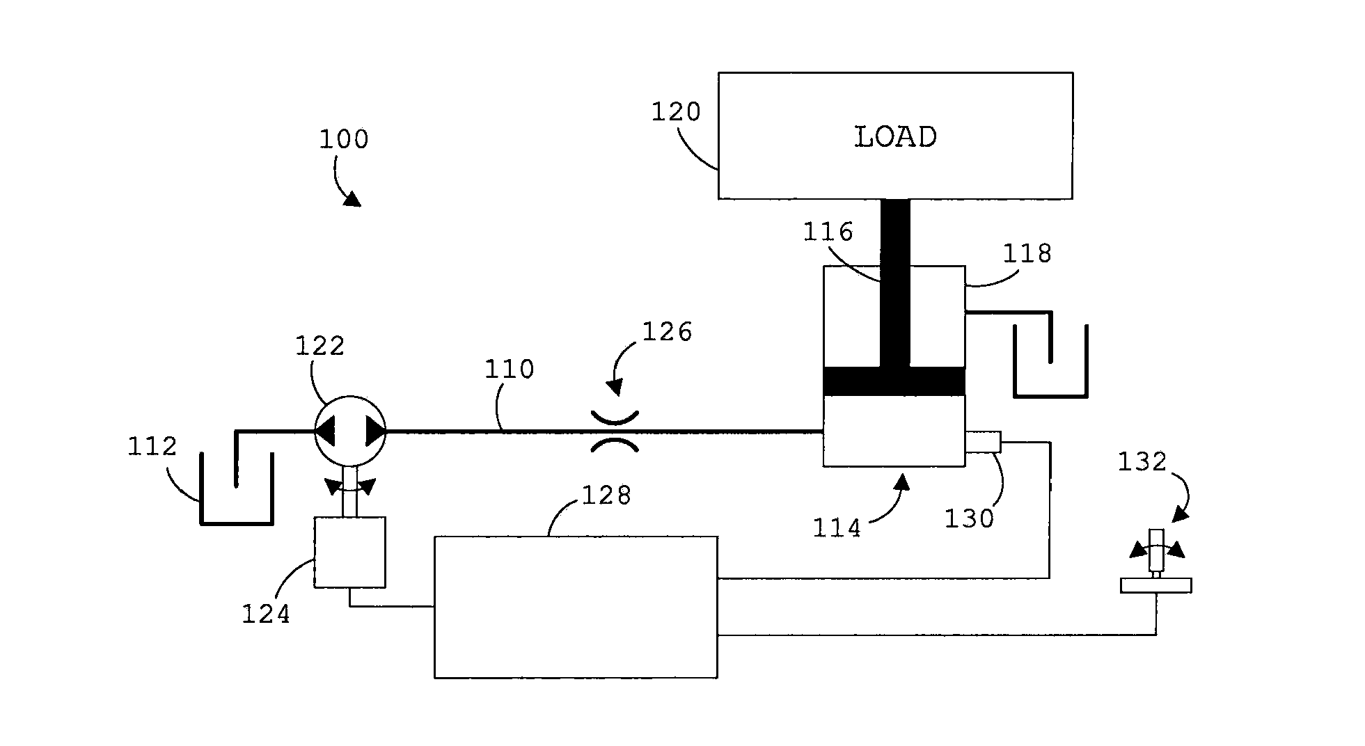
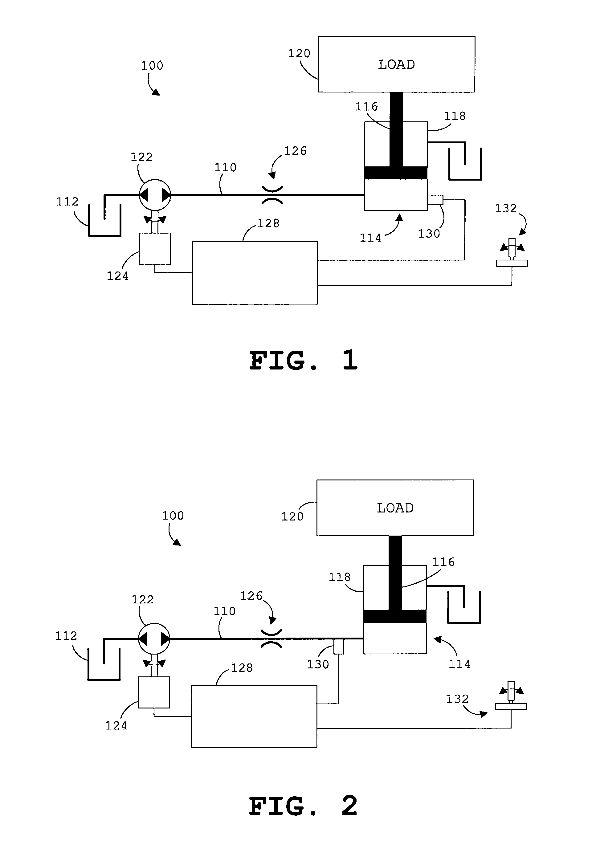
[0025]Referring first to FIGS. 1 and 2, a combined electronic and hydraulic schematic is illustrative of a hydraulic system 100 for a machine such as, for example, an earth moving or mining machine. The darker lines indicate hydraulic lines or components while the lighter lines indicate electrical connections.

[0026]With respect to the hydraulic components of the schematics, a hydraulic line 110 places a reservoir 112 on the left side of the schematics in fluid communication with a hydraulic cylinder 114 on the right side of the schematics. The hydraulic cylinder 114 includes a piston 116 actuatable within a cylinder 118 by a hydraulic fluid supplied from the reservoir 112 via the hydraulic line 110. The piston 116 is linked to a load 120, the load 120 comprising machine components including the piston 116 itself and / or separate items lifted by the machine components.

[0027]A pressure source in the form of a hydraulic pump 122 is located along the hydraulic line 110. When operated, th...


PUM


Abstract

A hydraulic system and a method of actively damping oscillations during actuation of a hydraulic cylinder in a hydraulic system is disclosed. The hydraulic cylinder is actuated by energizing a motor that rotatably drives a pump. The pump supplies a fluid to the hydraulic cylinder to actuate the cylinder. A pressure of the fluid is sensed during actuation of the hydraulic cylinder. A rotational speed of the motor is varied in response to the sensed pressure of the fluid. This varying of the rotational speed of the motor actively damps pressure oscillations during actuation of the hydraulic cylinder.

Description

CROSS-REFERENCE TO RELATED APPLICATION[0001]Not applicable.STATEMENT OF FEDERALLY SPONSORED RESEARCH OR DEVELOPMENT[0002]Not applicable.BACKGROUND OF THE INVENTION[0003]This invention relates to a hydraulic system. In particular, this invention relates to a hydraulic system that actively damps oscillations during the actuation of a hydraulic cylinder.[0004]Large industrial equipment, such as earth-moving machines, often utilize hydraulic systems to move heavy components and / or loads. Typically, a pump is used to supply fluid to a hydraulic cylinder having a movable piston. By supplying fluid to the hydraulic cylinder, the piston is extended and / or retracted to actuate a portion of the machine.[0005]Unfortunately, however, the hydraulic fluid may effectively behave as a spring if the fluid is sufficiently compressible and the load being moved is sufficiently heavy. The larger a load is, the greater its inertia. Particularly at the start or the end of a piston stroke, a large mass wil...

Claims


Application Information

Patent Timeline
IPC IPC(8): F15B11/04F15B21/12
CPCF15B7/006F15B2211/20515F15B2211/20538F15B2211/20561F15B2211/761F15B2211/6313F15B2211/6346F15B2211/6651F15B2211/27
Inventor VONDERWELL, MARK PHILLIP
Owner BUCYRUS INTERNATIONAL
Why Eureka
Try Eureka