
Apparatus, system, and method for a compact symmetrical transition structure for radio frequency applications

a transition structure and radio frequency technology, applied in the field of radio frequency applications, can solve the problems of difficult mounting of the substrate on the chassis of a typical consumer electronic product, difficult integration of a conventional planar dipole antenna in a multi-layer substrate, and large antenna size, and achieve the effect of high volume manufacturing

Active Publication Date: 2011-11-24
QUALCOMM INC
View PDF2 Cites 24 Cited by
  • Summary
  • Abstract
  • Description
  • Claims
  • Application Information

AI Technical Summary

Benefits of technology

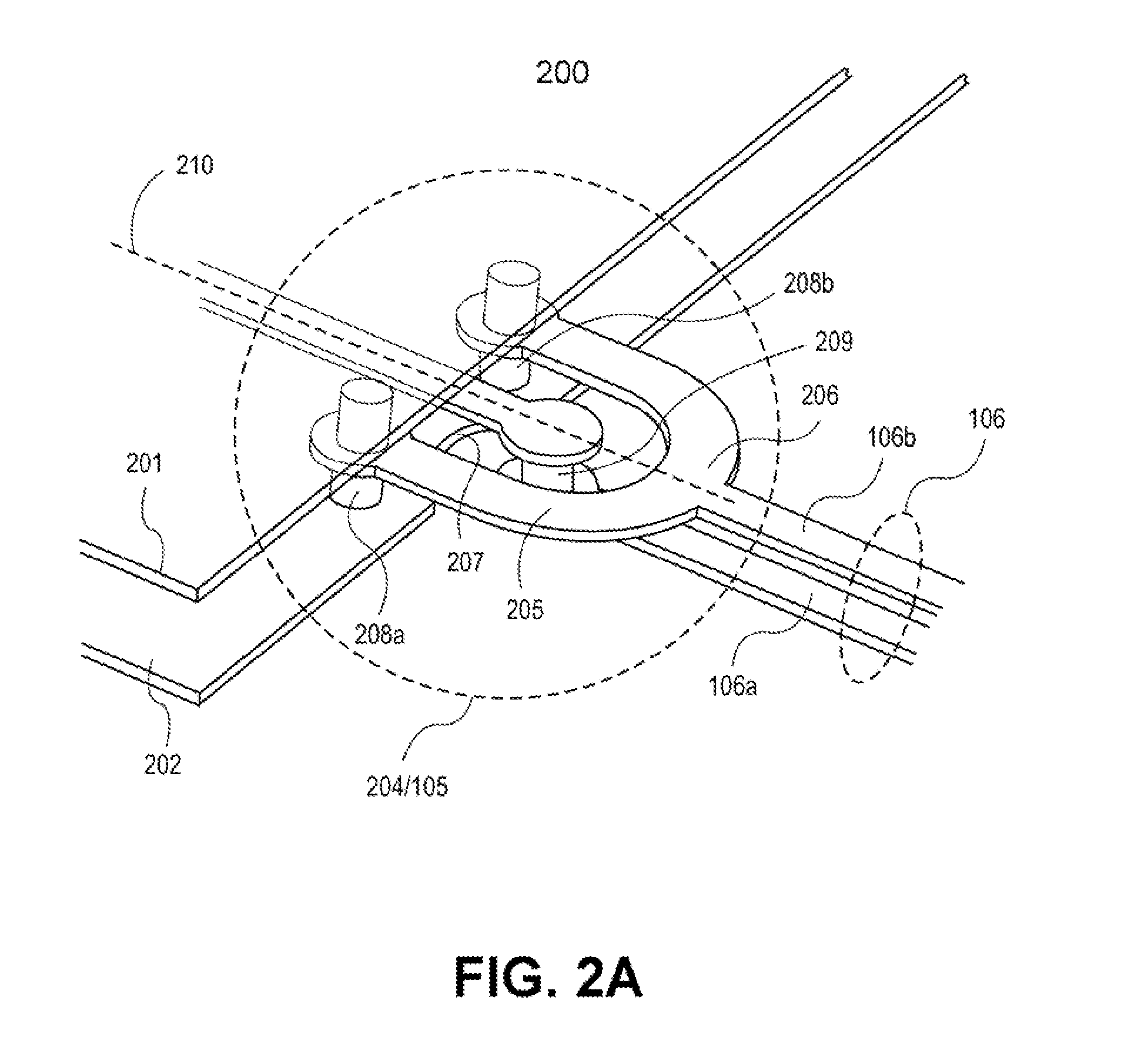
[0005]Described herein are embodiments of apparatus, system, and method for a compact symmetrical transition structure for Radio Frequency (RF) applications that allow integration of a non-planar antenna with a single-ended RF signal distributed on a signal plane that is positioned between two parallel ground planes resulting in a compact design for high volume manufacturing.

Problems solved by technology

This radiation direction makes it difficult for mounting the substrate on a chassis of a typical consumer electronic product where the radiation comes out only in a direction parallel to the substrate.
However, the integration of a conventional planar dipole antenna in a multi-layer substrate is challenging because the need for balanced feed to the conventional planar dipole antenna and removal of ground planes near the conventional planar dipole antenna make the total size of the antenna quite large.
Moreover, the large sized conventional planar dipole antennas, when packed in array topologies with driving RFICs in the same package on a common substrate, are challenging because of the large size to integrate within consumer electronic devices which are becoming smaller in size.

Method used


Image

  • Apparatus, system, and method for a compact symmetrical transition structure for radio frequency applications
  • Apparatus, system, and method for a compact symmetrical transition structure for radio frequency applications
  • Apparatus, system, and method for a compact symmetrical transition structure for radio frequency applications

Examples


Embodiment Construction

[0021]Described herein are embodiments of apparatus, system, and method for a compact symmetrical transition structure for Radio Frequency (RF) applications that allow integration of a non-planar antenna with a single-ended RF signal distributed on a signal plane that resides between two ground planes resulting in a compact design for high volume manufacturing.

[0022]FIG. 1 illustrates a high level radio frequency (RF) device 100 with integrated matching devices having a compact symmetrical transitional structure, according to one embodiment of the invention. In one embodiment, the RF device 100 comprises a first matching device 103 coupled to a second matching device 107 via a transmission feed 104, symmetrical transition structure 105, and a pair of broadside coupled lines (BCLs) 106. In one embodiment, the transmission feed 104 is positioned between two parallel ground planes (only top ground plane 102 is shown) having respective truncated edges 108.

[0023]In one embodiment, the tr...


PUM


Abstract

Described herein are an apparatus, system, and method having a compact symmetrical transition structure for RF applications. The apparatus comprises: first and second ground planes each of which having respective truncated edges, the first and second ground planes being parallel to one another and separated by a multi-layer substrate; a strip line positioned between the first and second ground planes; and a symmetrical transition structure, coupled to the strip line and the first and second ground planes near their respective truncated edges, and further coupled to a broadside coupled line (BCL).

Description

CLAIM OF PRIORITY[0001]The present patent application claims priority to and incorporates by reference the corresponding provisional Patent Application Ser. No. 61 / 347,776, titled, “SUBSTRATE INTEGRATED END-FIRE RF ANTENNA COMPATIBLE WITH RFIC PACKAGING” filed on May 24, 2010.FIELD OF THE INVENTION[0002]Embodiments of the invention relate generally to the field of radio frequency (RF) applications. More particularly, embodiments of the invention relate to an apparatus, system, and method for a compact symmetrical transition structure for RF applications.BACKGROUND[0003]For a multilayer substrate with one or more ground planes and single-ended signal distribution, as is typical at millimeter wave frequencies, patch antennas are used for easy integration with radio frequency integrated circuits (RFICs). While patch antennas are efficient in terms of radiation and only require a single-ended feed, they radiate mainly in the plane normal to the substrate. This radiation direction makes ...

Claims


Application Information

Patent Timeline
IPC IPC(8): H01P5/02
CPCH01P5/10H01Q9/285H01Q21/0081
Inventor ALI, MOHAMMED ERSHAD
Owner QUALCOMM INC
Learn More