Eureka AIR delivers breakthrough ideas for toughest innovation challenges, trusted by R&D personnel around the world.

Apparatus and Method for Treatment of a Contaminated Water-Based Fluid

Inactive Publication Date: 2011-11-24
KOLMIR WATER TECH
View PDF0 Cites 19 Cited by
  • Summary
  • Abstract
  • Description
  • Claims
  • Application Information

AI Technical Summary

Benefits of technology

[0017]It would be advantageous to have a method and apparatus which has a high efficiency of treatment and a deep level of purification.
[0055]The apparatus according to the present invention may have a low manufacturing cost.

Problems solved by technology

The filtration of suspended particles is usually a very difficult process, due to the strong interactions between the particles and fluid.
One of the disadvantages of porous filters is associated with clogging of the pores of the filter by larger particles which cannot pass through the pores.
Moreover, owing to an electric charge, even the particles with sizes smaller than the size of the filter pores can be clogged within the pores, due to the adhesion of the particles to the filter.
As a consequence of the clogging, either the flow rate of the fluid has to be gradually increased or a frequent flushing of the filters is necessary.
However, increasing the fluid flow rate can push through the filter even larger particles which would not pass through the pores at the original fluid flow rate.
As soon as the filter is clogged, it cannot provide sufficient filtering.
These interruptions of the filtering process lead to loss of efficiency of filtering, making the process expensive, and possibly requiring additional components for the filter system.
It should be noted that when a filter is interposed to the fluid flow through which the contaminated fluid can pass, the filtrate material of the fluid is retained on the filter and eventually clogs it up.

Method used


Image

  • Apparatus and Method for Treatment of a Contaminated Water-Based Fluid
  • Apparatus and Method for Treatment of a Contaminated Water-Based Fluid
  • Apparatus and Method for Treatment of a Contaminated Water-Based Fluid

Examples


example 1

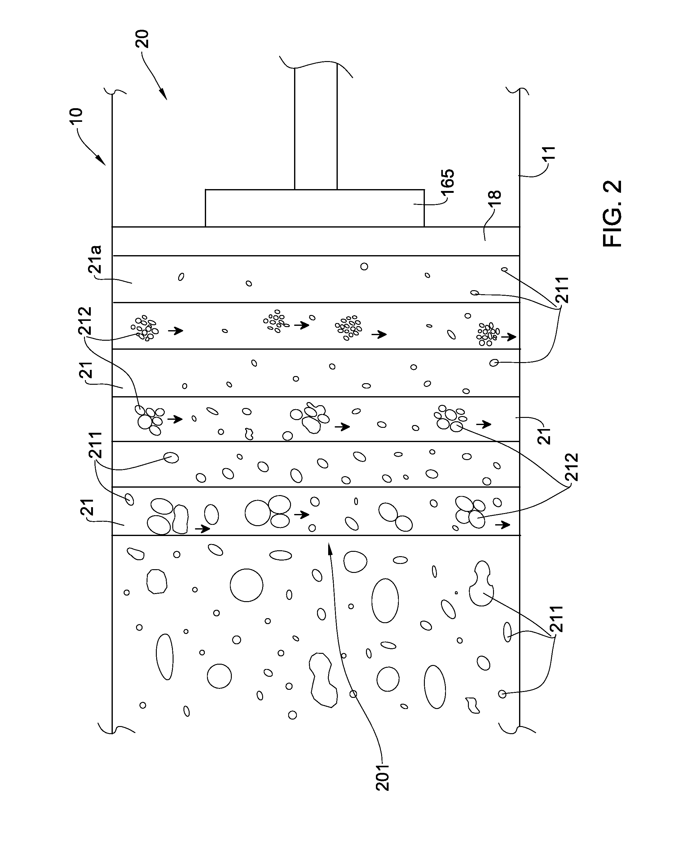
[0131]Process water from Geneva Lake probed in Geneva (Switzerland) was treated by the method and apparatus, according to one embodiment of the present invention. No preliminary mechanical, physicochemical or biological purification of the process water was performed in the treatment. The acoustic wave parameters of the apparatus were set as follows: the frequency of the acoustic wave was 15.3 kHz, the amplitude of the acoustic wave was 1.2 micrometers, the intensity of the acoustic wave was 0.72 Watt / cm2 and the treatment time was 0.03 seconds.

[0132]The chemical and electro-chemical properties of the process water and the pre-filtered fluid obtained after passing through the layers formed by the acoustic wave (before filtration with a filter unit) are presented in Table 2.

TABLE 2Exemplary chemical and electro-chemical properties of the probedprocess water and the pre-filtered fluid obtained by a method andapparatus of the present invention in accordance with one embodimentProcessPr...

example 2

[0134]Process water from Vltava River probed in Prague (Czech Republic) was treated by the same method and apparatus that was used in Example 1. No preliminary mechanical, physicochemical or biological purification of the process water was performed in the treatment. The acoustic wave parameters of the apparatus were set as follows: the frequency of the acoustic wave was 22 kHz, the amplitude of the acoustic wave was 2 micrometers, the intensity of the acoustic wave was 1 Watt / cm2 and the treatment time was 2 seconds.

[0135]The parameters of the process water-based fluid and pre-filtered fluid are presented in Table 3.

TABLE 3Exemplary chemical and electro-chemical properties of the probedprocess water and the pre-filtered fluid obtained by a method andapparatus of the present invention in accordance with one embodimentProcessPre-filteredNoItemfluid, mg / lfluid, mg / l1Total suspended solids, mg / l651.22Color index, deg51183pH7.27.394Total hardness, mEq / l0.90.95Carbonate hardness, microEq...


PUM

PropertyMeasurementUnit
Lengthaaaaaaaaaa
Lengthaaaaaaaaaa
Frequencyaaaaaaaaaa

Abstract

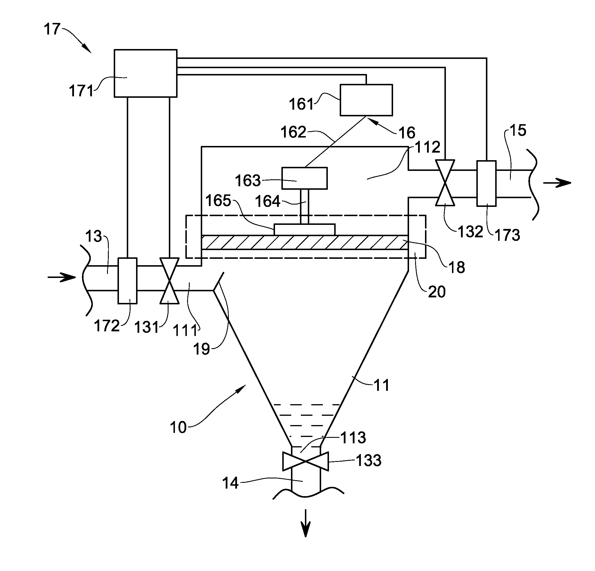
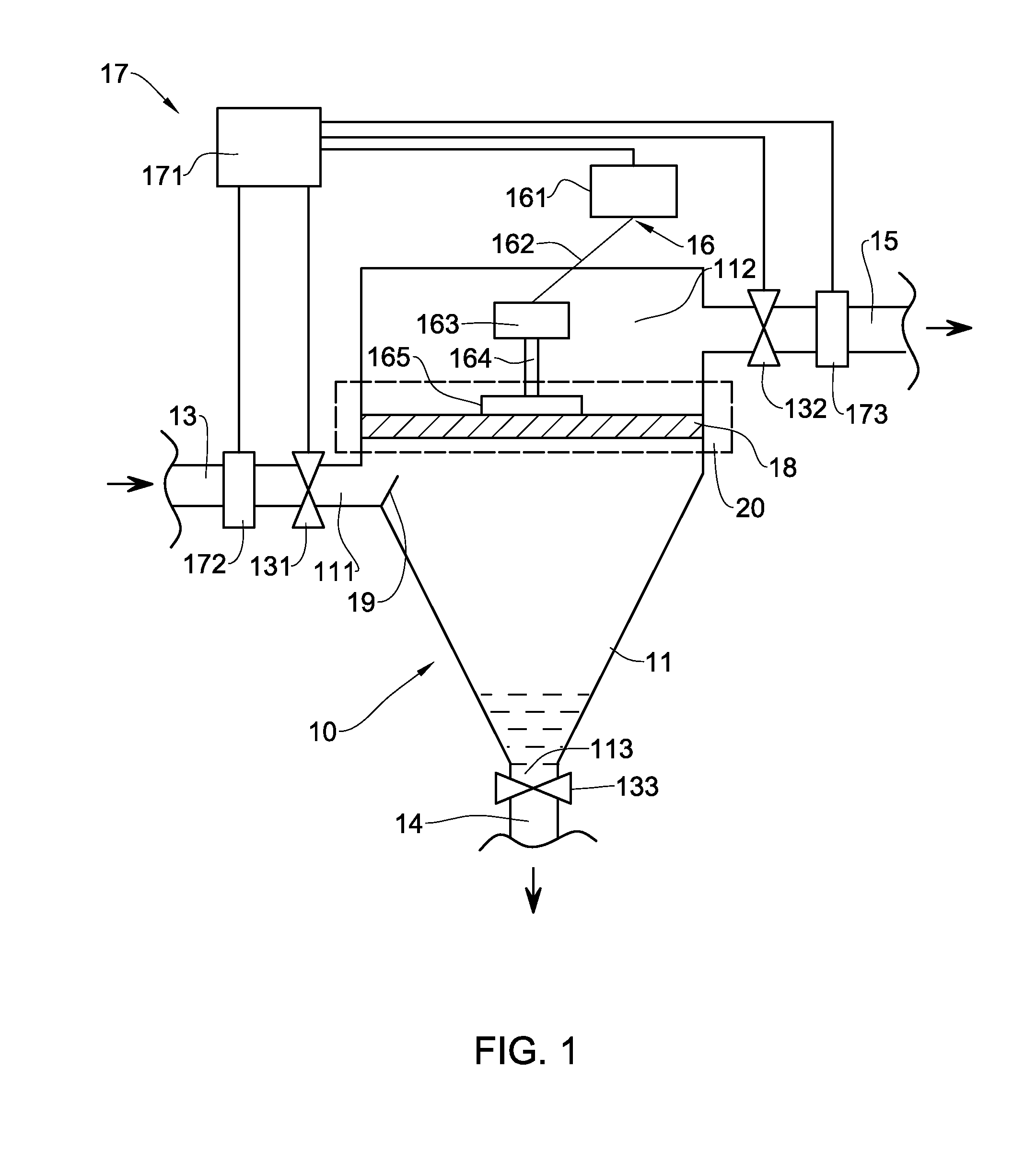
An apparatus and method for controllable separation of a purified fluid from a process water-based fluid containing at least one contaminating component are described. The apparatus comprises a housing having an inlet port for receiving the process water-based fluid through a controllable inlet valve, an outlet port for discharge of the purified fluid and a sludge port for discharge of a sludge fluid. The apparatus also includes an acoustic vibrator configured for generating a controllable acoustic wave having at least one adjustable parameter selected from frequency, amplitude and intensity. This acoustic vibrator creates at least one layer in the process water-based fluid dividing the process water-based fluid into a pre-filtered fluid and a sludge fluid. This layer is substantially perpendicular to a flow direction of said process water-based fluid. The layer comprises hydroxide radicals and oxygen species reacting with the contaminating component thereby transforming the component into radical form and oxidizing the component thereby causing binding of the component into insoluble aggregates which are precipitated within the sludge fluid. In addition, the apparatus comprises a filter unit disposed within the housing in a flow of the pre-filtered fluid from the layer to the outlet port.

Description

CROSS-REFERENCE TO RELATED APPLICATIONS[0001]This application is a Continuation application of International Application PCT / IL2009 / 000492 filed on May 17, 2009, which in turn claims priority to U.S. Provisional application 61 / 056,104 filed on May 27, 2008, both of which are to incorporated herein by reference in their entirety.FIELD OF THE INVENTION[0002]This invention relates to a technique for the purification of a contaminated water-based fluid, and more particularly to an apparatus and method for treatment of a contaminated water-based fluid.BACKGROUND OF THE INVENTION[0003]A significant amount of research and development has been undertaken in recent years towards environmental clean-up operations, and in particular to the treatment and purification of various fluids. A variety of techniques have been used in prior art to destroy and / or remove from the fluids various contaminating and toxic components, such as oil products, detergents, phenols, dyes, complexons, complexonates,...

Claims


Application Information

Patent Timeline
IPC IPC(8): C02F1/36
CPCC02F1/004C02F1/008C02F2305/023C02F2301/022C02F2209/29C02F2209/22C02F1/34C02F1/36C02F1/5236C02F1/72C02F9/00C02F2101/301C02F2101/308C02F2101/327C02F2101/345C02F2103/001C02F2103/007C02F2103/06C02F2103/08C02F2103/322C02F2103/325C02F2103/327C02F2209/001C02F2209/003C02F2209/04C02F2209/05C02F2209/055C02F2209/06C02F2209/07C02F2209/08C02F2209/10C02F2209/11C02F2209/14C02F2209/15C02F2209/16C02F2209/19C02F2209/20C02F1/001C02F1/44Y02A20/144Y02A20/131Y02A20/152
Inventor KOLODNY, YURI
Owner KOLMIR WATER TECH
Why Eureka
Eureka Blog
Learn More