Staple strip and staple cartridge

a staple strip and cartridge technology, applied in the field of interlinked staples, can solve the problems of preventing them from being accurately fed, and achieve the effects of reducing the number of staples, reducing the number of posture-by-load, and preventing adhesion degradation of the adhesion portion of the binding sh

Active Publication Date: 2011-11-24
MAX CO LTD
View PDF1 Cites 2 Cited by
  • Summary
  • Abstract
  • Description
  • Claims
  • Application Information

AI Technical Summary

Benefits of technology

[0005]The present invention is one solving such a problem and has an object to provide interlinked staples in which paper-made staples are interlinked and a staple cartridge housing these interlinked staples detachably with respect to a stapler, by which they are able to be accurately fed inside the stapler, it is possible to execute the cutoff of the staple and pass through the binding sheets accurately, it is possible to make the posture-by-load small, and it is possible to prevent adhesion degradation of adhesion portions for mutually bonding both the leg portions.
[0038]The staple cartridge relating to the present invention houses the interlinked staples each including the adhesion portion for both the leg portions in the staple housing unit, so that the adhesion portion for both the leg portions will not be exposed directly to the external atmosphere or various kinds of light beams, thereby preventing adhesion degradation. Also, there is provided, in the vicinity of at least one edge portion on the rear surface of each of the staples, with the adhesion portion for both the leg portions for mutually bonding both the leg portions in each of the interlinked staples housed in the staple cartridge, and the adhesion portion for both the leg portions is attached with the first release coated paper, which causes a state in which the adhesion portion for both the leg portions is protected. Consequently, it becomes possible to prevent adhesion degradation of the adhesion portion for both the leg portions for mutually bonding both the leg portions.

Problems solved by technology

H11-347966 have a problem such that they are deformed in the inside of the stapler, thereby preventing them from being accurately fed to a predetermined position thereof.

Method used


Image

  • Staple strip and staple cartridge
  • Staple strip and staple cartridge
  • Staple strip and staple cartridge

Examples


Embodiment Construction

[0129]Hereinafter, it will be explained with respect to exemplified embodiments of interlinked staples of the present invention with reference to the drawings.

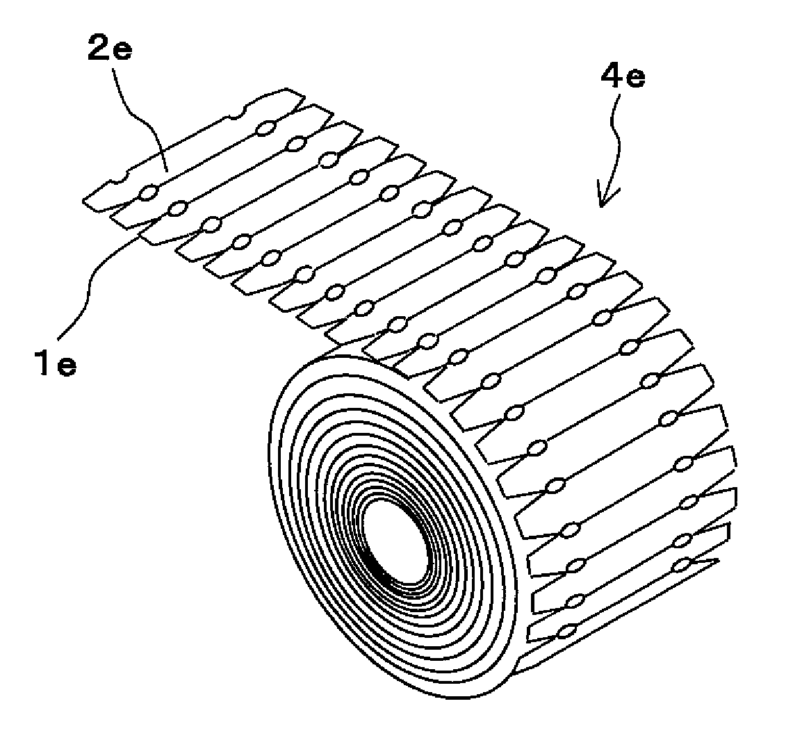
[0130]Interlinked staples 1 are ones in which a plurality of staples 2 are interlinked and are used with them being loaded in a stapler 3 mentioned later. The staple 2 positioned at the edge portion of the interlinked staples 1 is cut off by the stapler 3. The cut off staple is shaped by the stapler 3 in a shape in which both the edges thereof are bent to one direction and thereafter, pass through binding sheets, and both the passed leg portions are bent and mutually bonded. The binding sheets are bound in this manner.

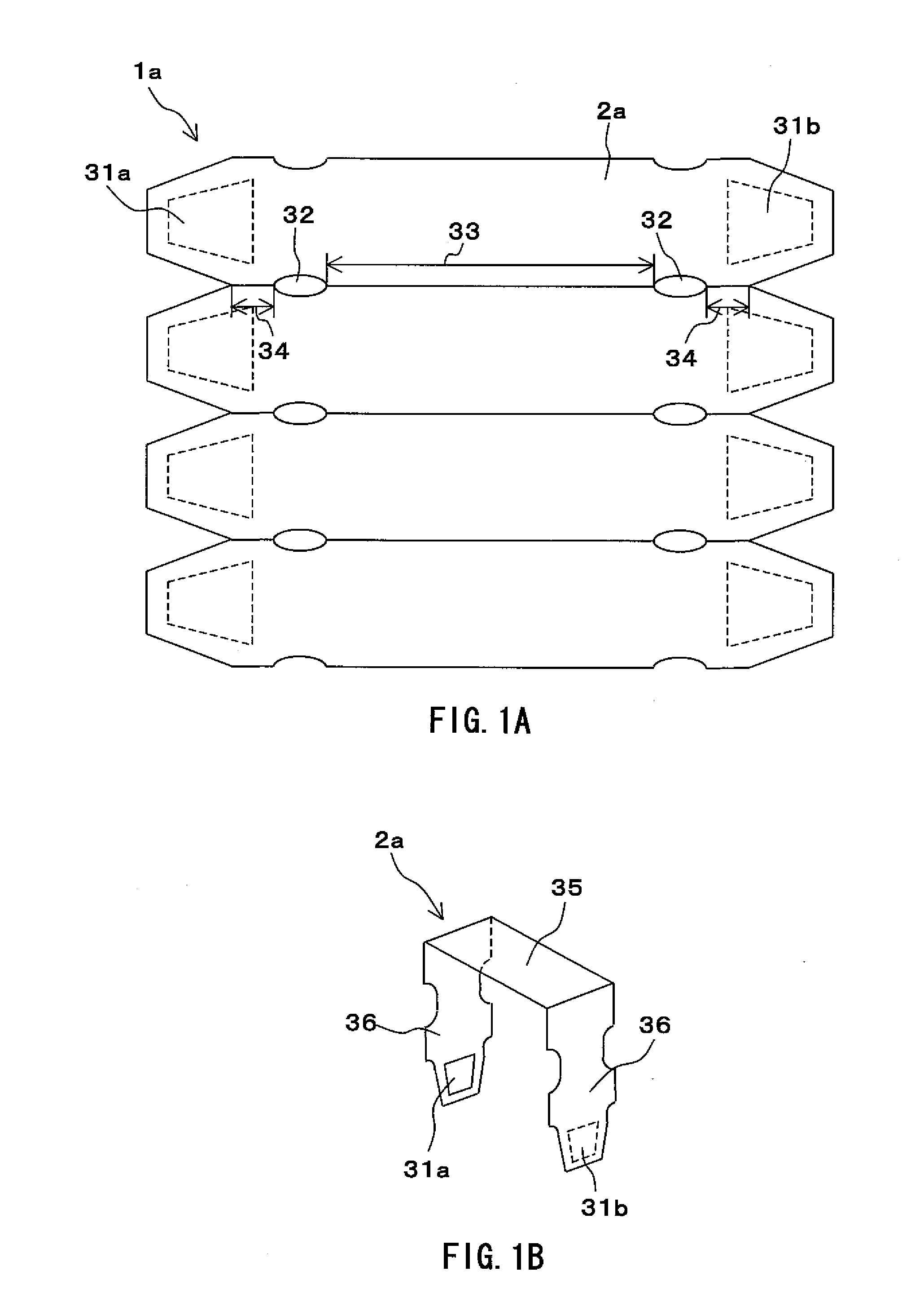
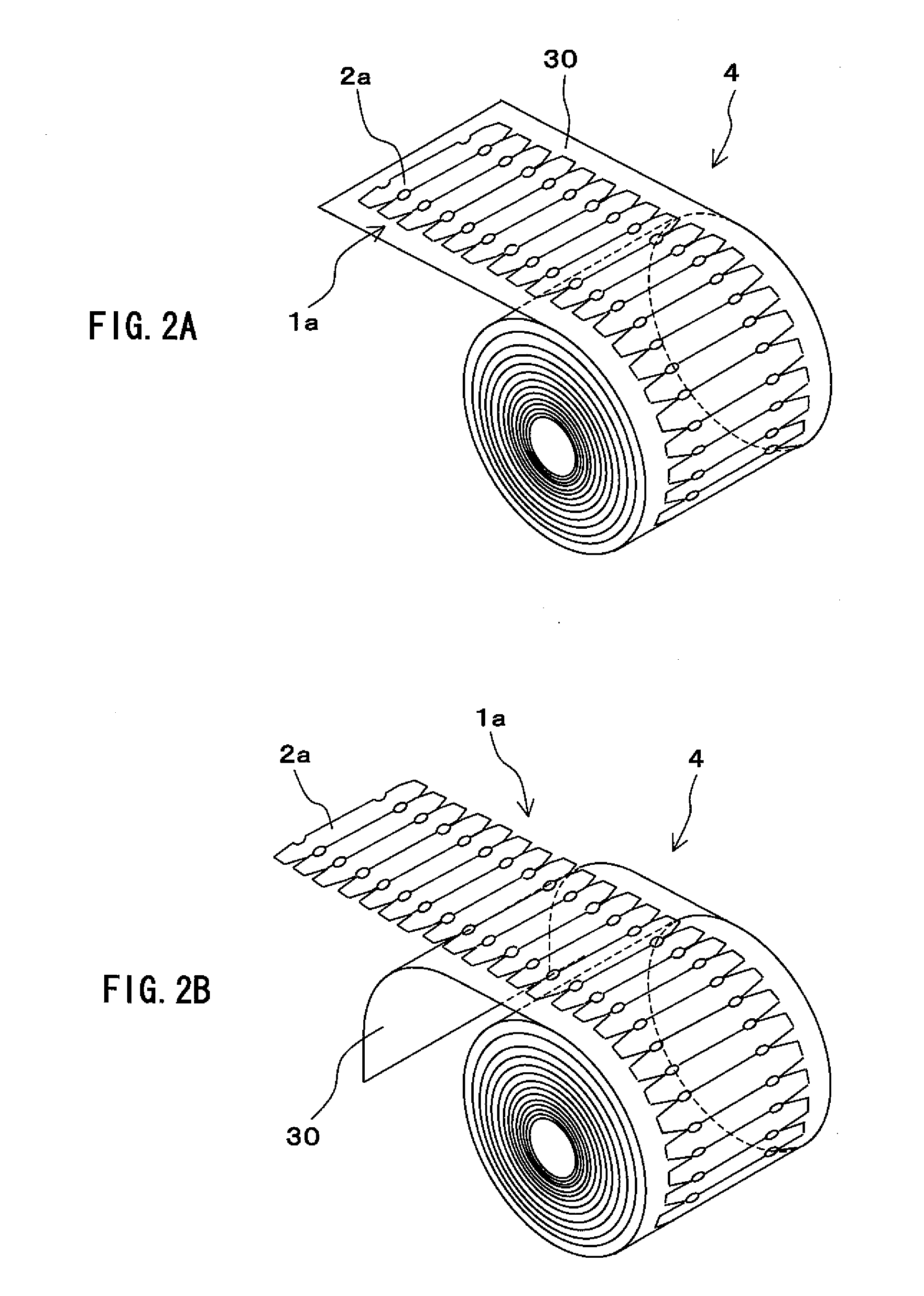
[0131]FIG. 1A, FIG. 1B, FIG. 2A and FIG. 2B are explanatory diagrams showing constitutions with respect to a staple 2a of a first example and with respect to interlinked staples 1a of a first example in which the staples 2a are interlinked. FIG. 1A is a plan view showing details of the interlinked staples 1a. FIG...


PUM


Abstract

To provide interlinked staples which are made possible to be fed accurately in the inside of a stapler and a staple cartridge which houses these interlinked staples.The interlinked staples 1a are constituted by interlinking a plurality of staples 2a each of which has an elongated and straight-formed shape. The vicinities of the edge portions in the longitudinal direction of the each staple 2a are formed in trapezoidal shapes, and the widths are tapered toward the tips thereof. Also, adhesion portions 31 coated with adhesive agent are provided on the rear surfaces of the vicinities of both the edge portions in the longitudinal direction of the each staple 2a. Also, there are provided elliptical feeding holes 32 at predetermined positions from both the edge portions of the side by which each staple 2a is interlinked. A portion between two feeding holes 32 is made to be a slit portion 33 and the respective staples 2a are cut off perfectly thereby. Portions on the outside of the two feeding holes 32 and until both the edge portions of the side by which each staple 2a is interlinked are operated as staple interlinking portions 34 and the respective staples 2a become in a state of being interlinked.

Description

TECHNICAL FIELD[0001]The present invention relates to interlinked staples in which a plurality of approximately straight lined staples are provided concurrently in parallel and mutually interlinked and relates to a staple cartridge which houses these interlinked staples and which is provided detachably with respect to a stapler. In more detail, it is made possible for the interlinked staples to be accurately fed into the inside of the stapler by providing for every staple with an engaged portion with which an engagement unit of feeding means engages.BACKGROUND ART[0002]From the past, there has been used a stapler that binds binding-sheets by means of a metal-made staple (needle). In case of binding paper-sheets by using such a stapler by means of the metal-made staple, there sometimes happens a case in which it is requested to separate the paper-sheets and the staple when the paper-sheets are processed by a paper shredder or for the reason of recycling. Also, in view of the safety p...

Claims


Application Information

Patent Timeline
Patent Type & Authority Applications(United States)
IPC IPC(8): B65D85/00F16B15/08
CPCB27F7/21B27F7/38F16B15/08B42P2241/28F16B15/0015B42B4/00
Inventor AOKI, AKIRA
Owner MAX CO LTD
Why Eureka
Try Eureka