
Seismic perimeter brace

Inactive Publication Date: 2011-11-24
USG INTERIORS LLC
View PDF14 Cites 33 Cited by
  • Summary
  • Abstract
  • Description
  • Claims
  • Application Information

AI Technical Summary

Benefits of technology

[0003]The invention provides a novel bracket particularly useful in higher seismic category geographic zones where suspended ceiling grid tees or runners are to be supported in close proximity to a wall other than by a conventional wall angle. Brackets of the invention, sometimes referred to as braces, can eliminate the need for suspension wires at the perimeter of a ceiling. Such wires can be difficult to install and, therefore, expensive for lack of conveniently accessible superstructure.
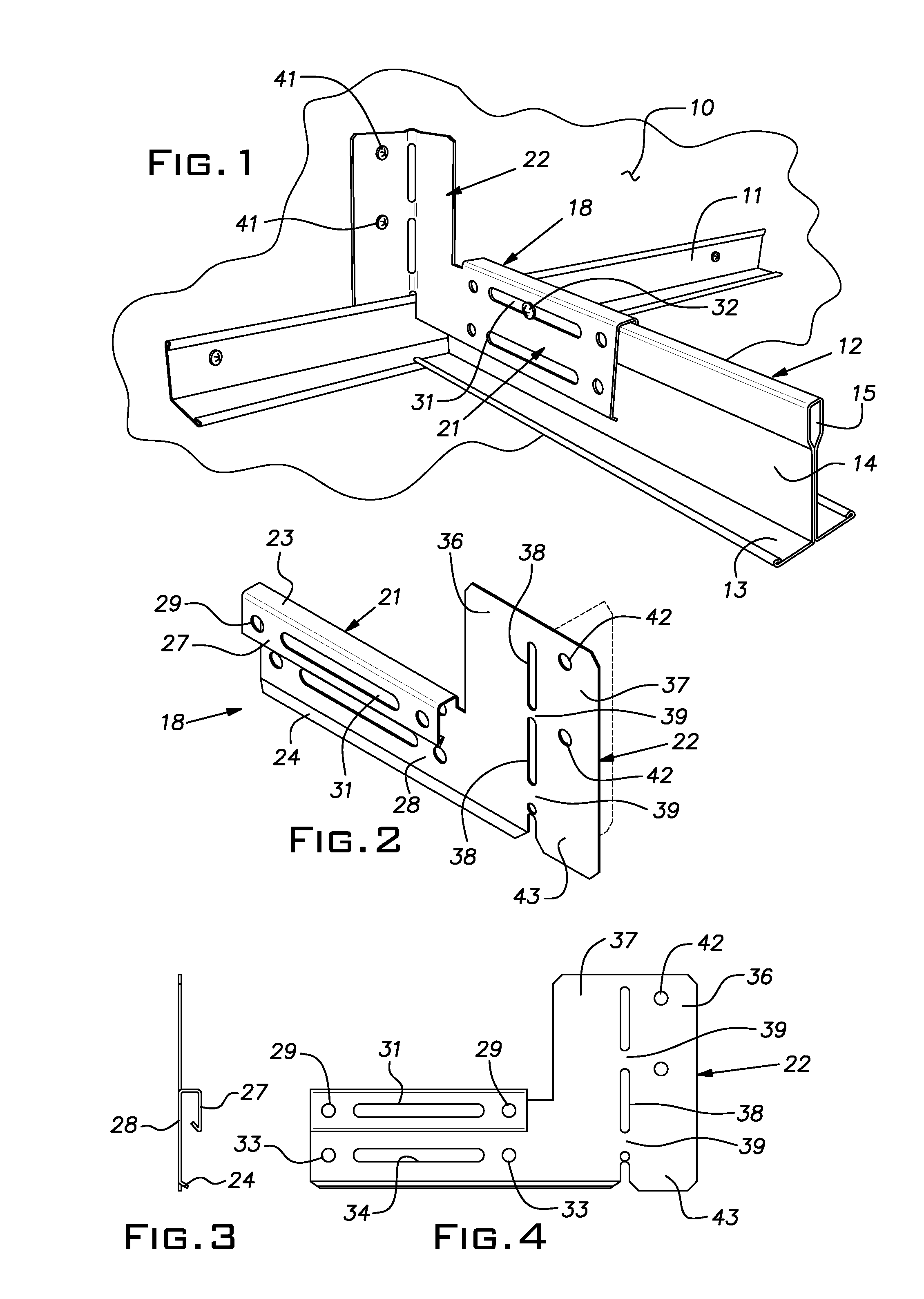
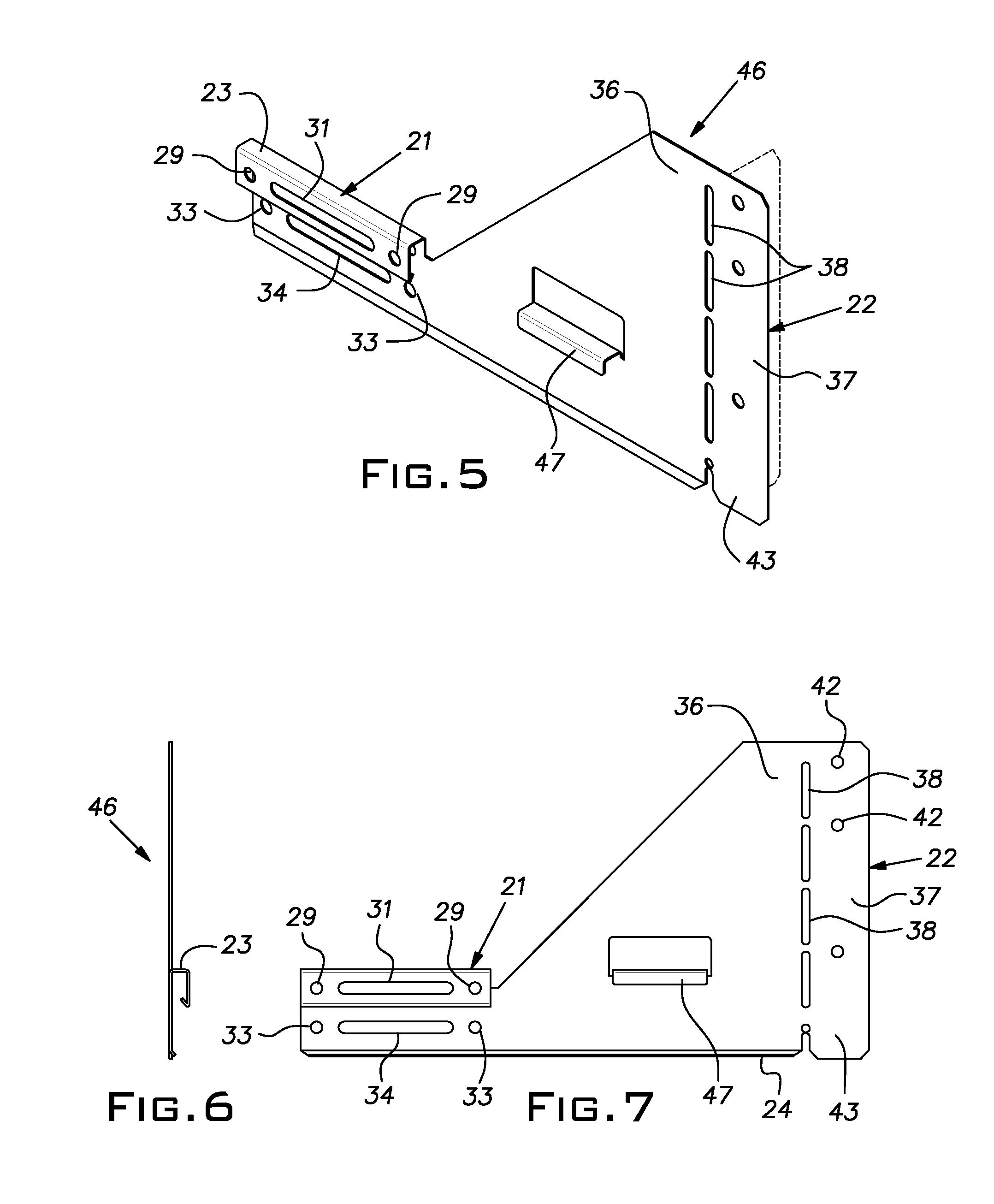
[0005]Ideally, the bracket optionally provides limited horizontal movement of the grid runner or a rigid connection of the grid runner to the wall. Horizontal movement is achieved with a slot in the bracket body that lies alongside a part of the grid runner and receives a fastener extending through the grid runner. Alternatively, the horizontal movement is accommodated by a depending pivotal arm integral with the bracket body. One part of the vertically extending portion is anchored flat against a surface of the wall at the boundary of the ceiling and another part of the vertically extending portion serves as a web between the wall anchored part and the horizontally extending portion of the bracket. The two parts of the vertically extending portion can be connected at a bend line defined by a zone weakened with a series of aligned apertures or slots in the sheet metal body. This construction permits the bracket to be bulk shipped in a “flat” configuration to occupy relatively small volume and be custom bent at the installation site by the installer to fit the intersection geometry of the ceiling grid and the wall especially if it is other than 90°.

Problems solved by technology

Such wires can be difficult to install and, therefore, expensive for lack of conveniently accessible superstructure.

Method used


Image

  • Seismic perimeter brace
  • Seismic perimeter brace
  • Seismic perimeter brace

Examples


Embodiment Construction

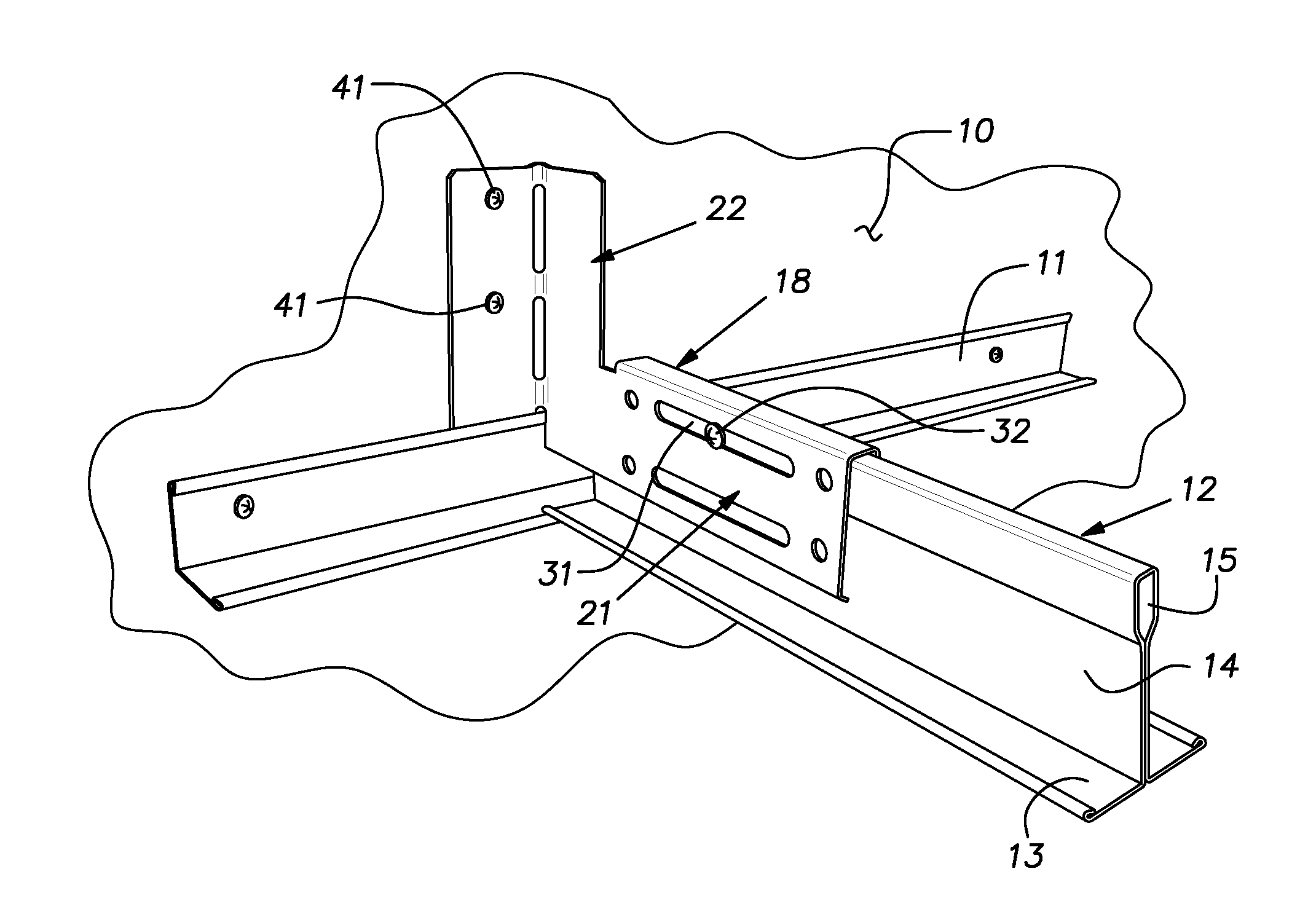
[0025]Referring now to the drawings and, in particular, to FIGS. 1-4, there is illustrated a vertical rigid wall 10 on which a conventional suspended ceiling wall angle 11 is mounted by suitable fasteners such as screws. The wall angle 11, conventionally roll-formed of sheet metal, lies at the perimeter and plane of a suspended ceiling grid represented by a grid runner or tee 12 of conventional construction. The grid runner 12, ordinarily of roll-formed sheet metal, has the general cross-section of an inverted T with a lower horizontal flange 13, vertical central web 14, and an upper polygonal hollow reinforcing bulb 15.

[0026]Typically, the wall angle 11 in several pieces is placed end-to-end to run along each wall surrounding the ceiling grid. Grid runners 12 are ordinarily spaced apart on two or four foot centers (or metric equivalent). In some categories of seismic rated geographic areas, it can be desired to support the peripheral grid runners 12 within 8″ of a wall 10. Often, t...


PUM


Abstract

A seismic bracket for supporting ends of suspended ceiling grid runners from a wall comprising a stamped sheet metal body, the body having a horizontally extending portion and a vertically extending portion, the vertically extending portion, in its installed position, rising above the top of a standard grid runner a distance at least 1½ times the height of such standard grid runner, the vertically extending portion having two sections generally coextensive in the vertical direction, a first section being integral with the horizontally extending portion and a second section arranged to be in a vertical plane that intersects a vertical plane occupied by the horizontally extending portion, the horizontally extending portion being arranged to support a grid runner to move longitudinally a limited distance, the second section of the vertically extending portion having an aperture for securing the bracket to the wall at a location substantially above the grid tee.

Description

BACKGROUND OF THE INVENTION[0001]The invention relates to suspended ceiling grid construction and, in particular, to a bracket for supporting peripheral ceiling grid runners from adjacent wall structure.PRIOR ART[0002]Geographic regions prone to or predicted to experience seismic events can benefit with construction elements that reduce the effects of these occurrences. In this context, suspended ceiling grids have been provided with various expedients to accommodate a sudden structural shift or series of shifts of limited amplitude and maintain sufficient integrity to keep ceiling panels carried on the grid from falling. There remains a need for a simple, quick, and effective way of supporting grid runners at the perimeter of a suspended ceiling apart from the standard wall angle. Often, the plenum above the ceiling adjacent its perimeter is occupied by utilities such as air ducts, electrical raceways and the like. These utilities and other objects can make it difficult to support ...

Claims


Application Information

Patent Timeline
IPC IPC(8): E04B1/98E04B9/18
CPCE04B9/067E04B9/30E04B9/127E04B9/08
Inventor UNDERKOFLER, ABRAHAM M.GULBRANDSEN, PEDER J.PAULSEN, MARK R.LEHANE, JAMES J.TEDESCO, LEE M.
Owner USG INTERIORS LLC
Learn More