
Acoustic sensor

a technology of acoustic sensors and electrode films, applied in the field of acoustic sensors, can solve the problems of moisture infiltrating the air gap between the diaphragm and the fixed electrode film, the acoustic vibration cannot be detected by the acoustic sensor, and the inability to form

Active Publication Date: 2011-11-17
MMI SEMICON CO LTD
View PDF3 Cites 31 Cited by
  • Summary
  • Abstract
  • Description
  • Claims
  • Application Information

AI Technical Summary

Benefits of technology

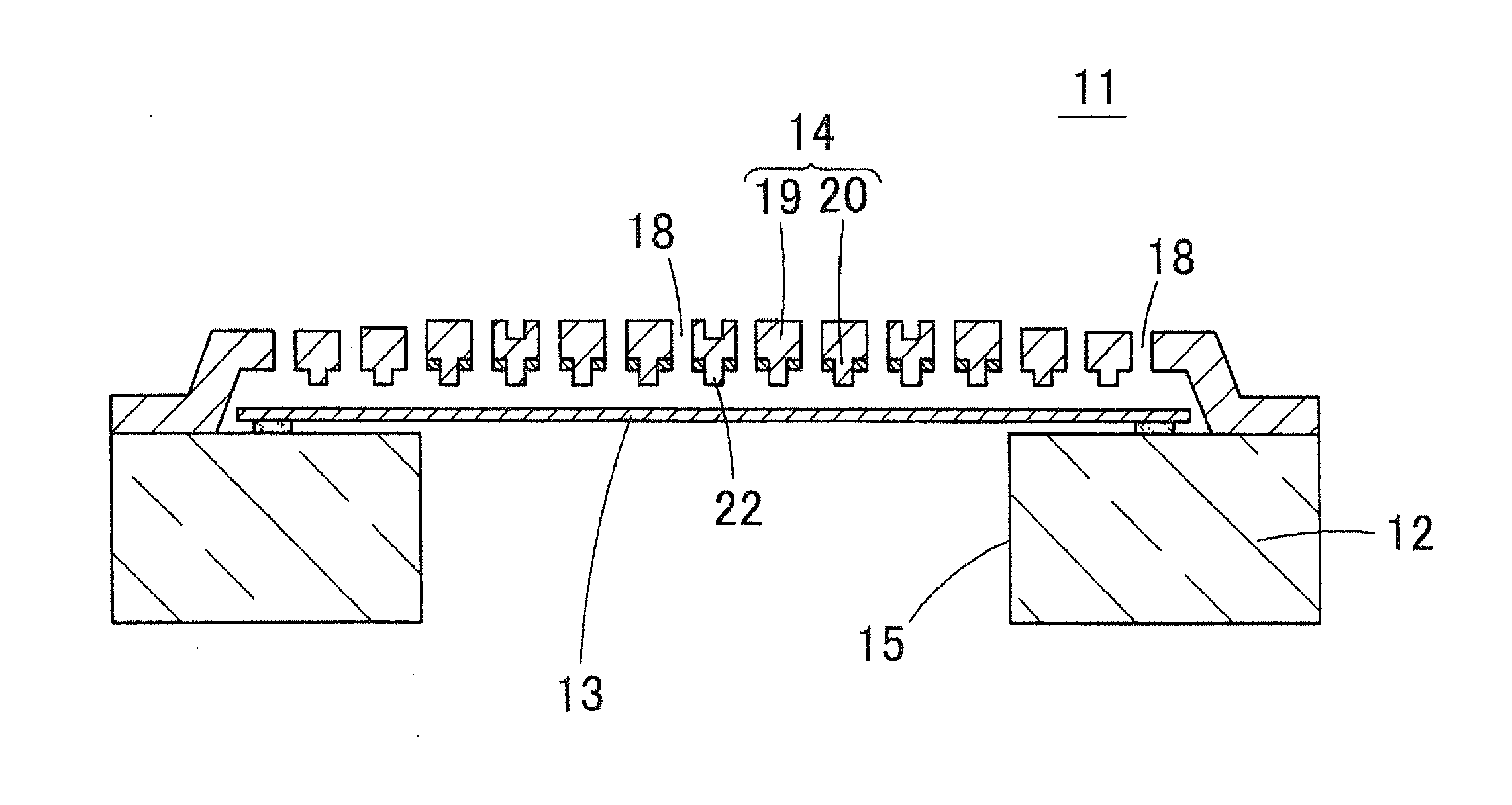
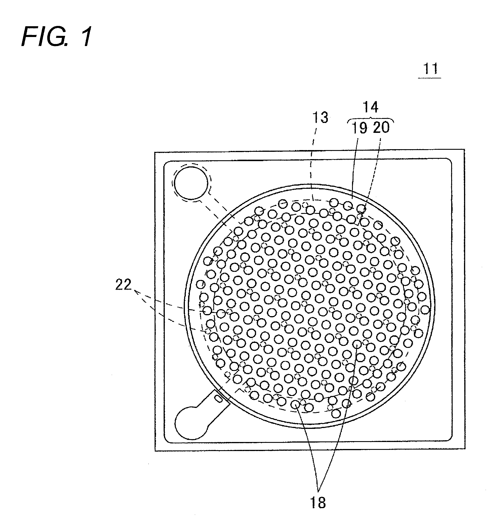
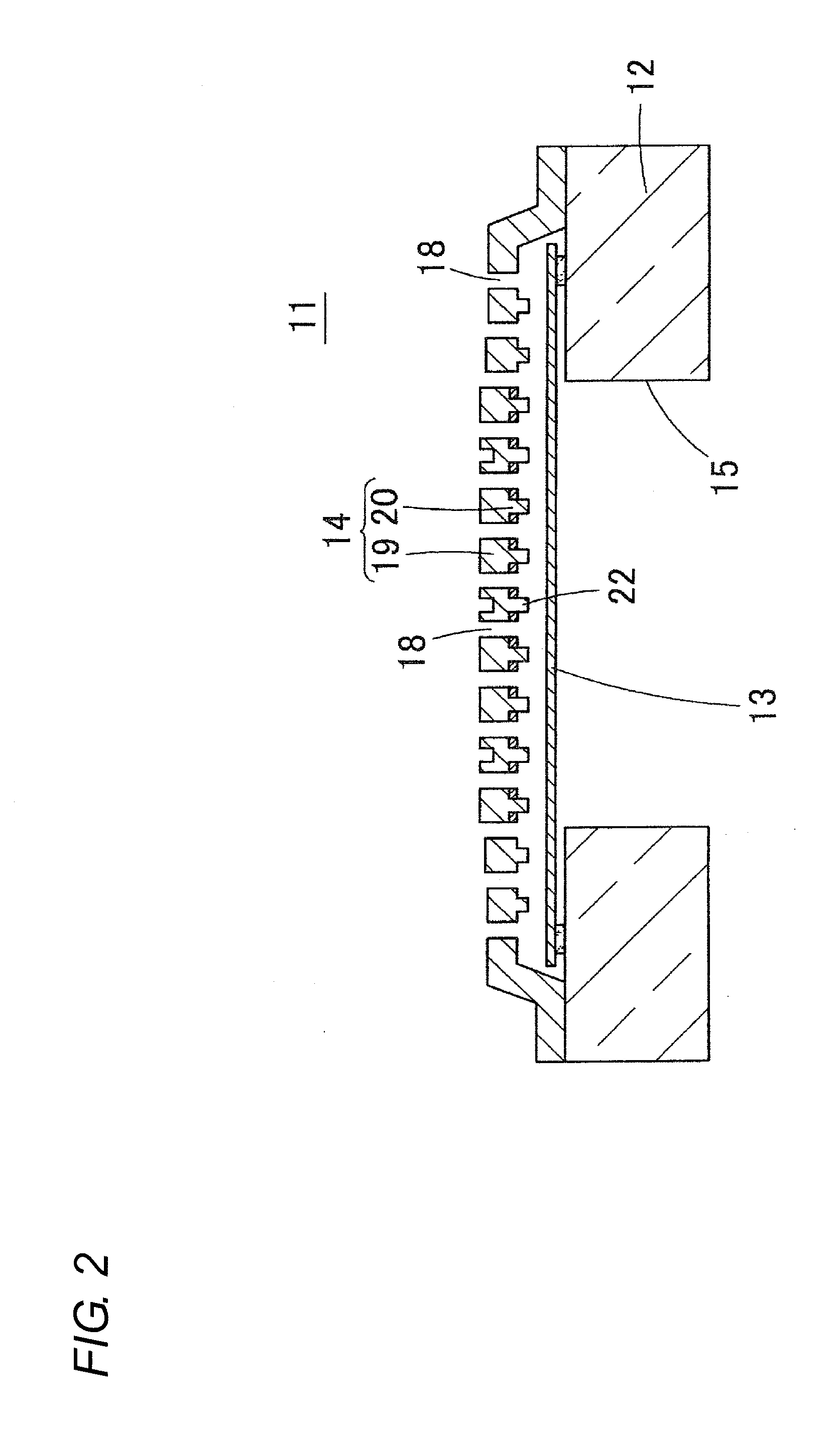
[0011]The holding force between the diaphragm 13 and the back plate 14 in the second stage of sticking is known to have correlation with a contacting area of the diaphragm 13 and the back plate 14. In other words, the contacting area of the diaphragm 13 and the stopper 22 becomes large and the holding force of the diaphragm 13 becomes large if the diameter of the stopper 22 is large even if the stopper 22 is arranged on the back plate 14. Therefore, sticking easily occurs if the diameter of the stopper 22 is large even if the stopper 22 is arranged on the back plate 14.
[0012]Therefore, the stopper 22 is to be arranged on the back plate 14, and the diameter of the stopper 22 is to be made as small as possible to reduce the contacting area of the diaphragm 13 and the back plate 14 in order to prevent sticking of the diaphragm 13.
[0013]However, in the drop accident at the time of actual use or the drop test, the diaphragm 13 hits the stopper 22 when the acoustic sensor 11 is dropped thereby applying a mechanical load on the diaphragm 13. Therefore, if the diameter of the stopper 22 is narrow, a large mechanical load applies on the diaphragm 13 and the diaphragm 13 may easily break when the acoustic sensor 11 is dropped and the diaphragm 13 hits the stopper 22.

Problems solved by technology

When the diaphragm sticks to the fixed electrode film, the acoustic vibration cannot be detected by the acoustic sensor because the vibration of the diaphragm is inhibited.
Moreover, moisture may infiltrate to the air gap between the diaphragm and the fixed electrode film due to humidity and water wetting even during the use of the acoustic sensor.
Therefore, in the conventional acoustic sensor, the performance of preventing sticking and the drop resistance property are in a contradicting relationship with each other, and an acoustic sensor that satisfies both properties could not be formed.
Japanese Unexamined Patent Publication No. 2008-301430 discloses the acoustic sensor in which the interval of the stopper is differed depending on the region to arrange the stopper, but the performance of preventing sticking and the drop resistance property cannot be simultaneously satisfied with such a technique.

Method used


Image

  • Acoustic sensor
  • Acoustic sensor
  • Acoustic sensor

Examples


first embodiment

[0042]The structure of an acoustic sensor 31 according to a first embodiment of the present invention will be described with reference to FIGS. 3 to 7. FIG. 3 is a plan view showing the acoustic sensor 31 of the first embodiment. FIG. 4 is a cross-sectional view of the acoustic sensor 31. FIG. 5 is a bottom view of a back plate 14. FIG. 6 is a plan view of a state in which the back plate 14 is removed from the acoustic sensor 31. FIG. 7 is a bottom view of the back plate 14 in which acoustic holes 38 are not shown and only stoppers 42a, 42b are shown.

[0043]The acoustic sensor 31 is a capacitance type element formed using a MEMS technique, where a diaphragm 33 (vibration electrode film) is arranged on an upper surface of a silicon substrate 32 (semiconductor substrate) through an anchor 37, and a back plate 34 is fixed thereon through a microscopic air gap (void), as shown in FIG. 4.

[0044]A back chamber 35 (hollow portion) passing through from a front surface to a rear surface is ope...

second embodiment

[0066]FIG. 11 is a schematic cross-sectional view showing an acoustic sensor 61 according to a second embodiment of the present invention. In the acoustic sensor 31 of the first embodiment, two types of stoppers 42a, 42b having different diameters are arranged on the lower surface of the back plate 34, but three or more types of stoppers having different diameters may be arranged.

[0067]In the acoustic sensor 61 shown in FIG. 11, a stopper 42e having the smallest diameter is arranged at the outermost peripheral area E, a stopper 42d having the second smallest diameter is arranged in an outer peripheral area D on the inner side of the outermost peripheral area E, and a stopper 42c having the largest diameter is arranged in an internal area C on the inner side of the outer peripheral area D at the lower surface of the back plate 34.

third embodiment

[0068]FIG. 12 is a schematic cross-sectional view showing an acoustic sensor 62 according to a third embodiment of the present invention. In the acoustic sensor 31 of the first embodiment, the stoppers 42a, 42b are arranged on the back plate 34, but the stoppers 42a, 42b are arranged on the upper surface of the diaphragm 33 in the acoustic sensor 62 of the third embodiment. In the acoustic sensor 62 as well, the stopper 42b having a small diameter is arranged at the outer peripheral area, and the stopper 42a having a large diameter is arranged in the internal area at the upper surface of the diaphragm 33. As a result, the impact resistance of the acoustic sensor 62 can be enhanced, and at the same time, the sticking of the diaphragm 33 can be prevented in the acoustic sensor 62 as well. In FIG. 12, a hole is formed in the fixed electrode film 40 at the area facing the distal end of the stopper 42a, 42b, so that the upper surface of the diaphragm 33 and the fixed electrode film 40 ar...


PUM


Abstract

A diaphragm for sensing sound pressure faces a back plate including a plate portion and a fixed electrode film to form a capacitance type acoustic sensor. The back plate is opened with acoustic holes for passing vibration, and is arranged with a plurality of stoppers in a projecting manner on a surface facing the diaphragm. The stopper arranged in an outer peripheral area of the back plate has a small diameter, and the stopper arranged in an internal area has a large diameter. Thus, sticking of the diaphragm is prevented, and the diaphragm is less likely to break by impact when the sensor is dropped.

Description

BACKGROUND OF THE INVENTION[0001]1. Technical Field[0002]The present invention relates to acoustic sensors, and specifically to a MEMS (Micro Electro Mechanical Systems) type acoustic sensor manufactured using a MEMS technique.[0003]2. Related Art[0004]A capacitance type acoustic sensor is disclosed in Japanese Patent No. 4338395. In the acoustic sensor of Japanese Patent No. 4338395, a capacitor is configured by facing a thin film diaphragm and a fixed electrode film arranged in a back plate through a microscopic air gap. When the diaphragm vibrates by acoustic vibration, the gap distance between the diaphragm and the fixed electrode film changes by such vibration, and hence the acoustic vibration can be detected by detecting the change in electrostatic capacitance between the diaphragm and the fixed electrode film.[0005]In such a capacitance type acoustic sensor, the diaphragm sometimes fixes to the fixed electrode film (hereinafter a state or a phenomenon in which the diaphragm i...

Claims


Application Information

Patent Timeline
IPC IPC(8): H01L29/84
CPCG01H11/06H04R19/005H04R19/04H04R31/006G01H3/00
Inventor KASAI, TAKASHI
Owner MMI SEMICON CO LTD
Learn More