Switching element and application of the same
- Summary
- Abstract
- Description
- Claims
- Application Information
AI Technical Summary
Benefits of technology
Problems solved by technology
Method used
Image
Examples
first embodiment
[0032]FIG. 1 is a cross-sectional view schematically showing a switching element (photoassisted switching element) of the first embodiment of the invention. As illustrated in the drawing, the switching element comprises a first electrode 4 and a second electrode 5 provided on an insulating substrate 1, in which these electrodes are disposed in a line with interval therebetween on the insulating substrate 1.
[0033]The first electrode 4 is composed of a first electrode electric conductor part 2 and a first electrode ionic conductor part 3, and the first electrode ionic conductor part 3 is formed, as laminated on the first electrode electric conductor part 2.
[0034]Between the first electrode 4 and the second electrode 5, disposed is a photoresponsive film 9 so as to fill up the space between the electrodes, more concretely, so as to fill up the space between the first electrode ionic conductor part 3 of the first electrode 4 and the second electrode 5. The photoresponsive film 9 is so d...
second embodiment
[0044]FIG. 2 is a cross-sectional view schematically showing a switching element (photoassisted switching element) of the second embodiment of the invention. In this embodiment, the constitutive components common to those in the first embodiment are given the same reference numerals or signs.
[0045]As illustrated in the figure, the switching element comprises a first electrode 4 and a second electrode 5 formed on an insulating substrate 1. The first electrode 4 is composed of a first electrode electric conductor part 2 and a first electrode ionic conductor part 3, and the first electrode ionic conductor part 3 is formed, as laminated on the first electrode electric conductor part 2. The second electrode 5 is composed of a transparent electric conductor.
[0046]Between the first electrode 4 and the second electrode 5, disposed is a photoresponsive film 9 so as to fill up the space between the electrodes; and in the region of the light-receiving part of the photoresponsive film 9, the fi...
third embodiment
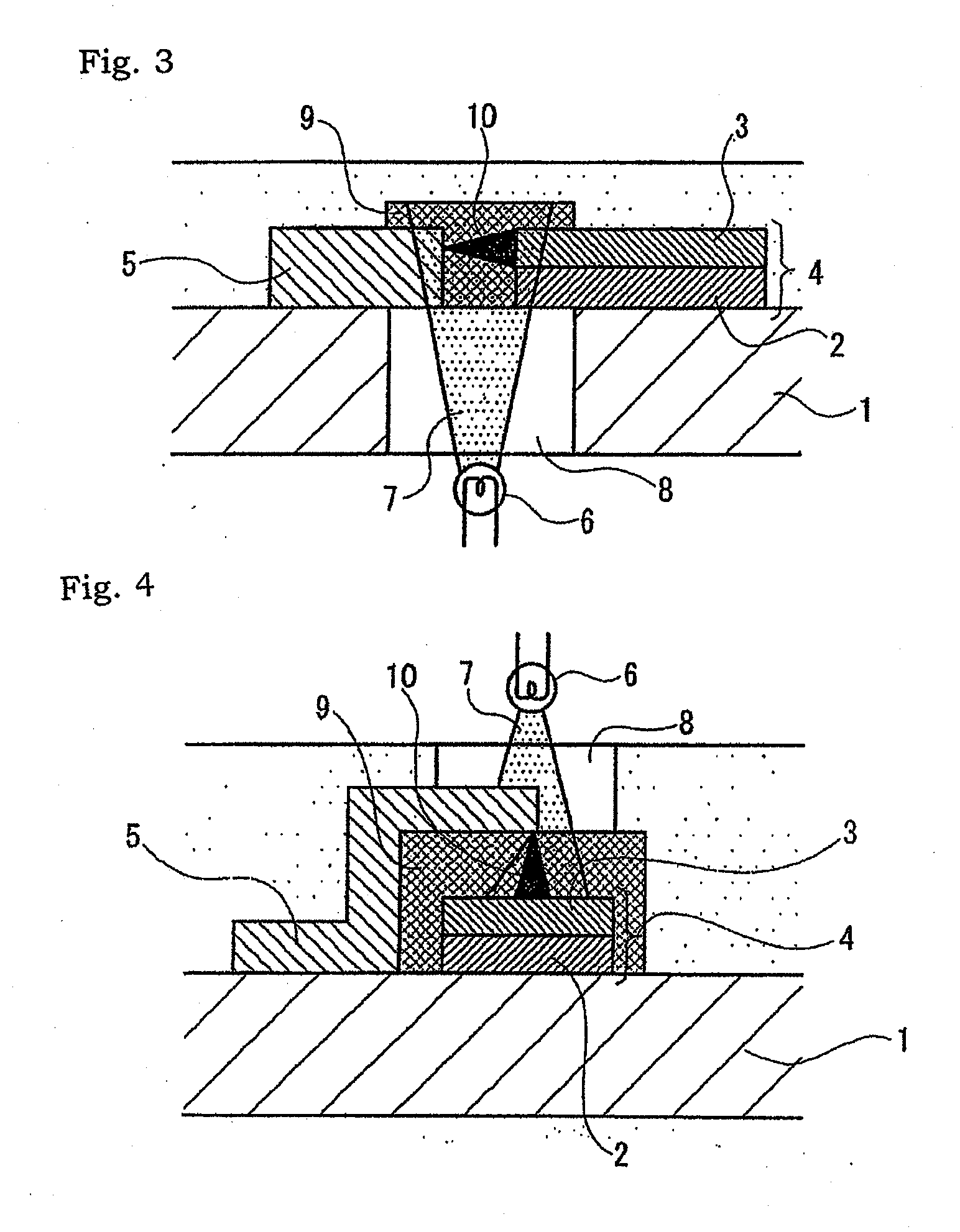
[0057]FIG. 3 is a cross-sectional view schematically showing a switching element (photoassisted switching element) of the third embodiment of the invention. In this embodiment, the constitutive components common to those in the first embodiment are given the same reference numerals or signs.
[0058]As illustrated in the figure, the switching element comprises a first electrode 4 and a second electrode 5 formed on an insulating substrate 1, in which these electrodes are disposed in a line with interval therebetween on the insulating substrate 1.
[0059]The first electrode 4 is composed of a first electrode electric conductor part 2 and a first electrode ionic conductor part 3, and the first electrode ionic conductor part 3 is formed, as laminated on the first electrode electric conductor part 2.
[0060]Between the first electrode 4 and the second electrode 5, disposed is a photoresponsive film 9 so as to fill up the space between the electrodes, more concretely, so as to fill up the space ...
PUM
 Abstract
Description
Claims
Application Information
 - R&D
- Intellectual Property
- Life Sciences
- Materials
- Tech Scout
- Unparalleled Data Quality
- Higher Quality Content
- 60% Fewer Hallucinations
Browse by: Latest US Patents, China's latest patents, Technical Efficacy Thesaurus, Application Domain, Technology Topic, Popular Technical Reports.
© 2025 PatSnap. All rights reserved.Legal|Privacy policy|Modern Slavery Act Transparency Statement|Sitemap|About US| Contact US: help@patsnap.com


