
Electroformed bipolar plates for fuel cells

a fuel cell and bipolar plate technology, applied in the field of bipolar plate assembly, can solve the problems of reducing the service life of the fuel cell, so as to improve the service life and reduce the cost. the effect of cost, efficient and robust structure and optimized electrical conta

Inactive Publication Date: 2011-10-27
GM GLOBAL TECH OPERATIONS LLC
View PDF8 Cites 7 Cited by
  • Summary
  • Abstract
  • Description
  • Claims
  • Application Information

AI Technical Summary

Benefits of technology

The patent describes a cost-effective and efficient bipolar plate assembly for fuel cells that has a strong structure and maximizes electrical contact between the plates while minimizing material usage and waste. The assembly includes two electroformed unipolar plates that are bonded together by multiple conductive plugs made of electroplated material. The method for preparing the assembly involves plating a substrate with a pattern and then placing two plated polymer sheets together, followed by applying a thickness of plating material to selectively bond the sheets together. This results in a highly effective and durable bipolar plate assembly for fuel cells.

Problems solved by technology

It is possible to achieve a desired minimal thickness of the substrate, but at a tradeoff to cost and to undesirable material properties.
For example, as a composite sheet is molded to a thinner dimension, it becomes more brittle and harder to work.
Additionally, a thinner composite sheet is often less desirable because high carbon content may cause a thinner sheet to become porous.
Similarly, as a metal sheet is thinned in multiple steps by drawing or rolling the sheet, it also becomes brittle or work hardened after each step, and requires annealing prior to further working.
Thus, a higher manufacturing cost is associated with a thinner substrate material.
A thinner metal substrate also limits the depth of any flow channel due to metal stretch limitations.
Additionally, conventional processes of forming the plates from the metal sheet material result in nearly half of the material being discarded as scrap.

Method used


Image

  • Electroformed bipolar plates for fuel cells
  • Electroformed bipolar plates for fuel cells
  • Electroformed bipolar plates for fuel cells

Examples


Embodiment Construction

[0022]The following detailed description and appended drawings describe and illustrate various embodiments of the invention. The description and drawings serve to enable one skilled in the art to make and use the invention, and are not intended to limit the scope of the invention in any manner. In respect of the methods disclosed, the steps presented are exemplary in nature, and thus, the order of the steps is not necessary or critical.

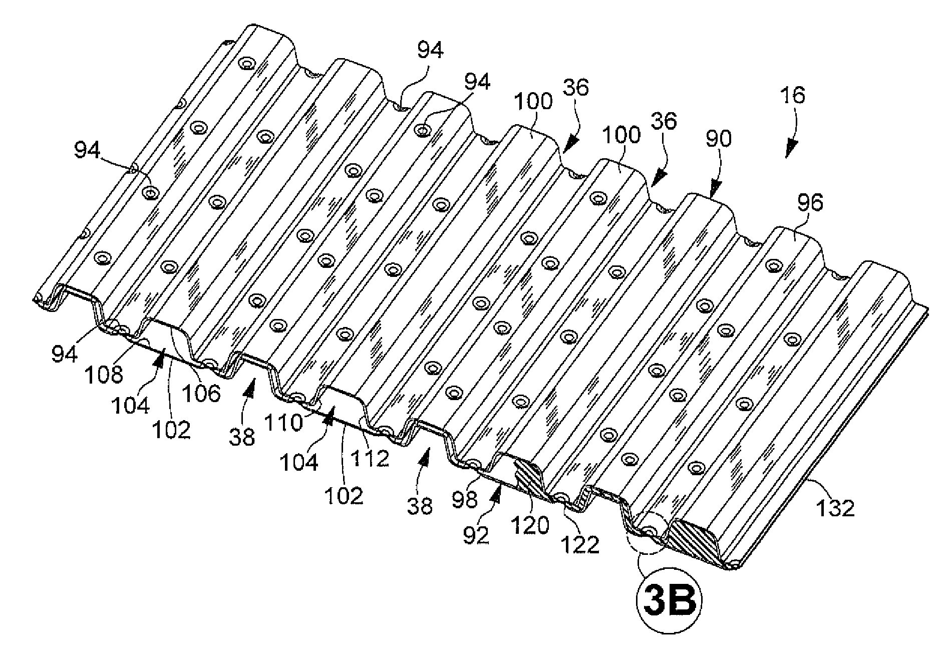
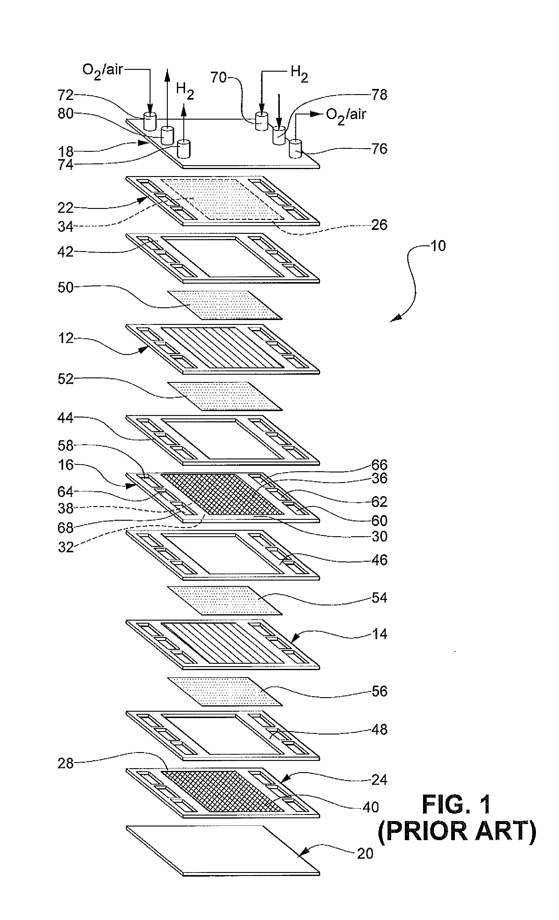
[0023]FIG. 1 illustrates a PEM fuel cell stack 10 according to the prior art. For simplicity, only a two-cell stack (i.e. one bipolar plate) is illustrated and described in FIG. 1, it being understood that a typical fuel cell stack will have many more such cells and bipolar plates. The fuel cell stack 10 includes a pair of membrane electrode assemblies (MEAs) 12, 14 separated by an electrically conductive bipolar plate 16. The MEAs 12, 14 and the bipolar plate 16 are stacked between a pair of clamping plates 18, 20 and a pair of unipolar end plates 22...


PUM

PropertyMeasurementUnit
thicknessaaaaaaaaaa
thicknessaaaaaaaaaa
thicknessaaaaaaaaaa

Abstract

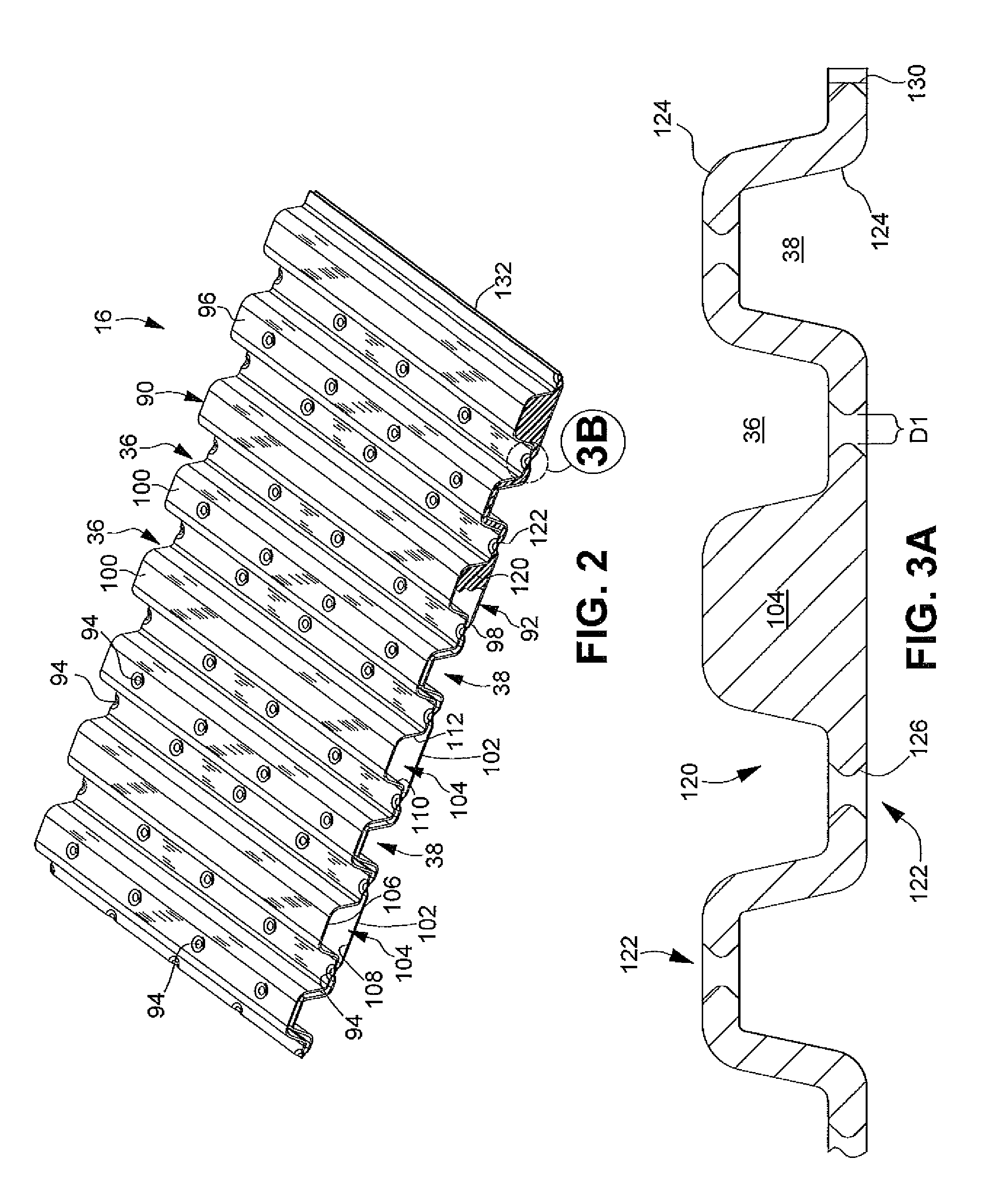
A bipolar plate assembly for a fuel cell is provided. The bipolar plate assembly includes a first electroformed unipolar plate disposed adjacent a second electroformed unipolar plate. The first and second unipolar plates are bonded by a plurality of localized electrically and thermally conductive plugs by electroplated material deposited within apertures formed in the substrates onto which the unipolar plates are electroformed. A method for forming the bipolar plate assembly is also described.

Description

FIELD OF THE INVENTION[0001]The present disclosure relates to fuel cell stacks and, more particularly, to a bipolar plate assembly and methods for preparing bipolar plates for fuel cell stacks.BACKGROUND OF THE INVENTION[0002]Fuel cells can be used as a power source in many applications. For example, fuel cells have been proposed for use in automobiles as a replacement for internal combustion engines. In proton exchange membrane (PEM) type fuel cells, a reactant such as hydrogen is supplied as a fuel to an anode of the fuel cell, and a reactant such as oxygen or air is supplied as an oxidant to the cathode of the fuel cell. The PEM fuel cell includes a membrane electrode assembly (MEA) having a proton transmissive, non-electrically conductive, proton exchange membrane. The proton exchange membrane has an anode catalyst on one face and a cathode catalyst on the opposite face. The MEA is often disposed between “anode” and “cathodediffusion media or diffusion layers that are formed f...

Claims


Application Information

Patent Timeline
Patent Type & Authority Applications(United States)
IPC IPC(8): H01M8/24B05D5/12C25D5/00H01M4/64
CPCH01M8/0247H01M8/0256Y02E60/50H01M8/241H01M8/248H01M8/0273H01M8/0267H01M8/242H01M8/2483
Inventor FLY, GERALD W.HEALY, JOHN P.GOEBEL, STEVEN G.
Owner GM GLOBAL TECH OPERATIONS LLC
Learn More