Powder/particulate material agitator

Active Publication Date: 2011-10-20
TSUKASA
View PDF35 Cites 8 Cited by
  • Summary
  • Abstract
  • Description
  • Claims
  • Application Information

AI Technical Summary

Benefits of technology

[0006]The blender disclosed in Patent Literature 1 is, however, required to make the return flow of the powder / particulate material from the rotary valve 6 through the two-way valve 8 and the return pipe 9 into the vessel 4. This arrangement makes the structure of the blender rather complicated and increases the overall height of the blender to have difficulty in input of the powder / particulate material. There is also limitation in increasing the efficiency of blending. One alternative structure may provide a gate device between the blender and a screw feeder to eliminate any dead space where the powder / particulate material is not blended. This alternative arrangement, however, makes the structure of the blender rather complicated and increases the overall height of the blender to have difficulty in input of the powder-particulate material. Either of these structures requires time- and labor-consuming cleaning of the blender, the rotary valve, and the gate device.
[0007]By taking into account at least part of the issue discussed above, there are requirements for enabling size reduction and simplification of a powder / particulate material agitator and preventing powder / particulate material from being accumulated in any dead space. There is also a requirement for reducing the height of a powder / particulate material discharger of the powder / particulate material agitator, so as to reduce the overall height of the agitator and facilitate the input of the powder / particulate material. There are further requirements for preventing contamination with the remaining powder / particulate material, remarkably reducing the cleaning cost of the agitator, and enhancing the stirring efficiency.
[0011]The technique of the present invention is applicable to any of high concentration transportation, medium concentration transportation, and low concentration transportation. Here the term “concentration” represents a mixing ratio of the amount of the powder / particulate material to the amount of the gas in the transportation pipe. The variation in setting of the concentration varies the settings of the gas pressure and the transportation speed. These settings are all relative settings and do not have any standard setting criteria. The higher concentration (i.e., the higher mixing ratio of the powder / particulate material) advantageously gives the higher stability of the transportation gas pressure.
[0016]The aspect of the invention discussed above enables size reduction and simplification of the powder / particulate material agitator to reduce the manufacturing cost. The above aspect of the invention also prevents the powder / particulate material from remaining (being accumulated) in dead space to enhance the stirring efficiency, while reducing the required height for a discharger of the agitator.

Problems solved by technology

This arrangement makes the structure of the blender rather complicated and increases the overall height of the blender to have difficulty in input of the powder / particulate material.
There is also limitation in increasing the efficiency of blending.
This alternative arrangement, however, makes the structure of the blender rather complicated and increases the overall height of the blender to have difficulty in input of the powder-particulate material.
Either of these structures requires time- and labor-consuming cleaning of the blender, the rotary valve, and the gate device.

Method used


Image

  • Powder/particulate material agitator
  • Powder/particulate material agitator
  • Powder/particulate material agitator

Examples


Embodiment Construction

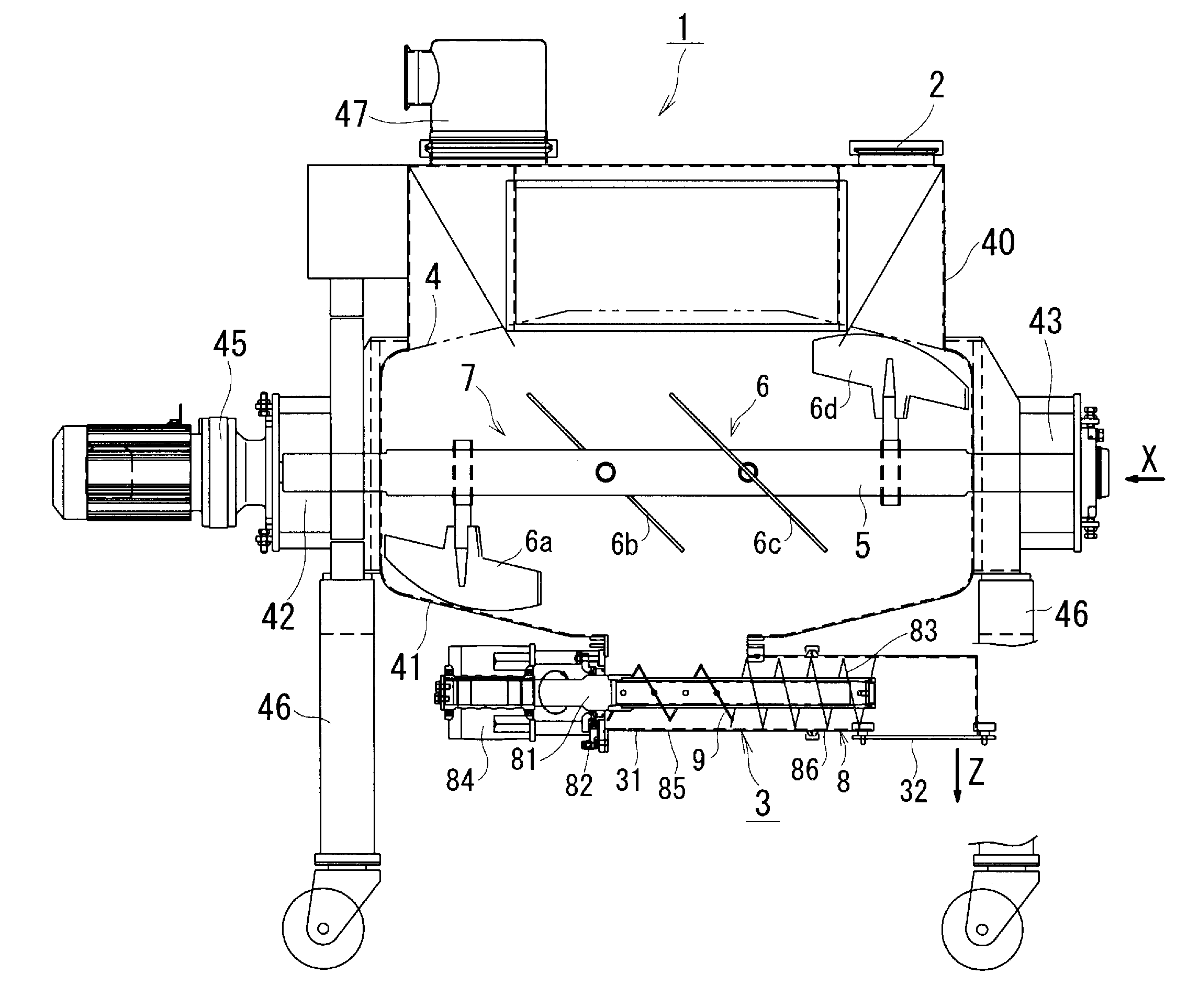
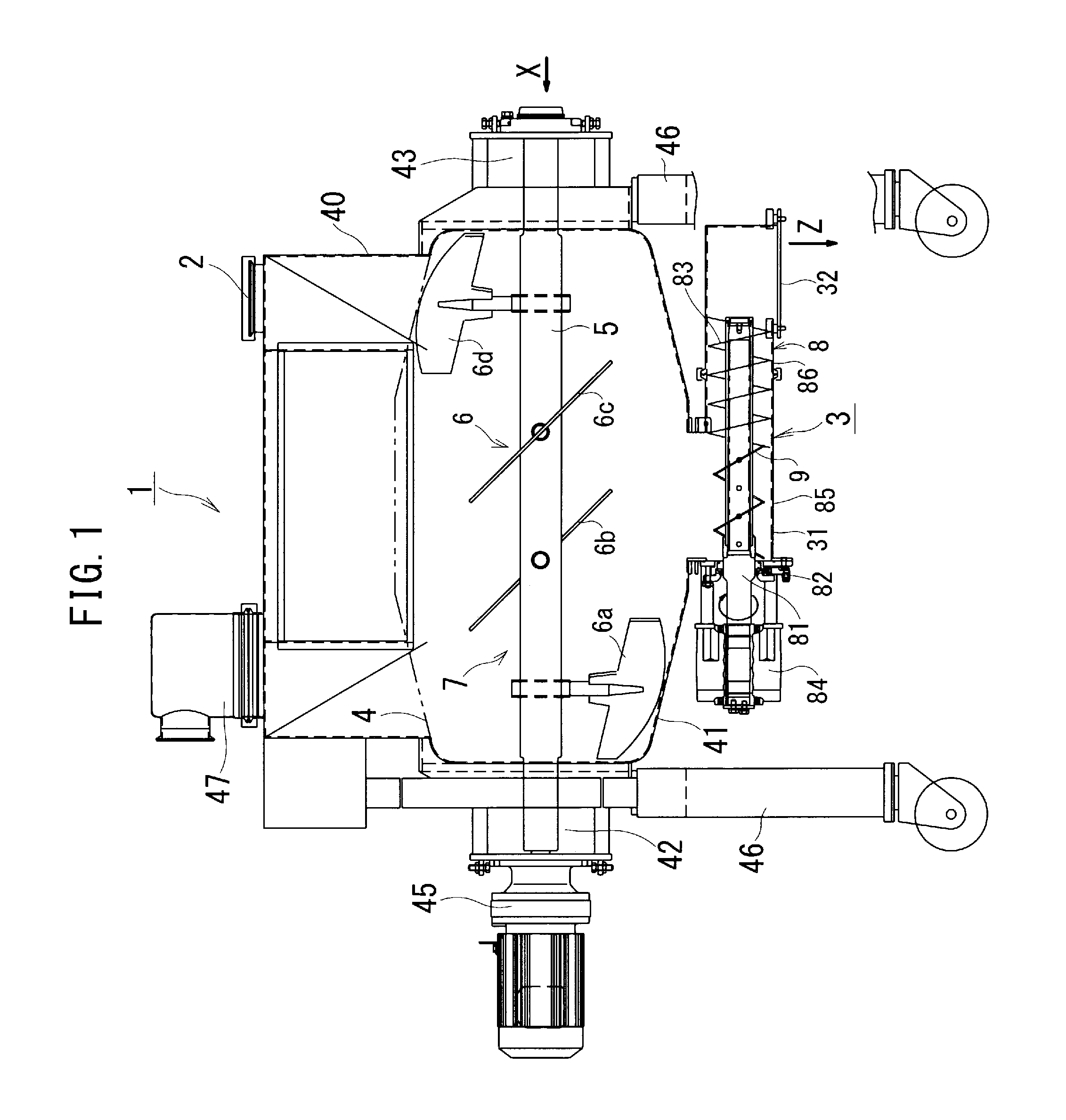
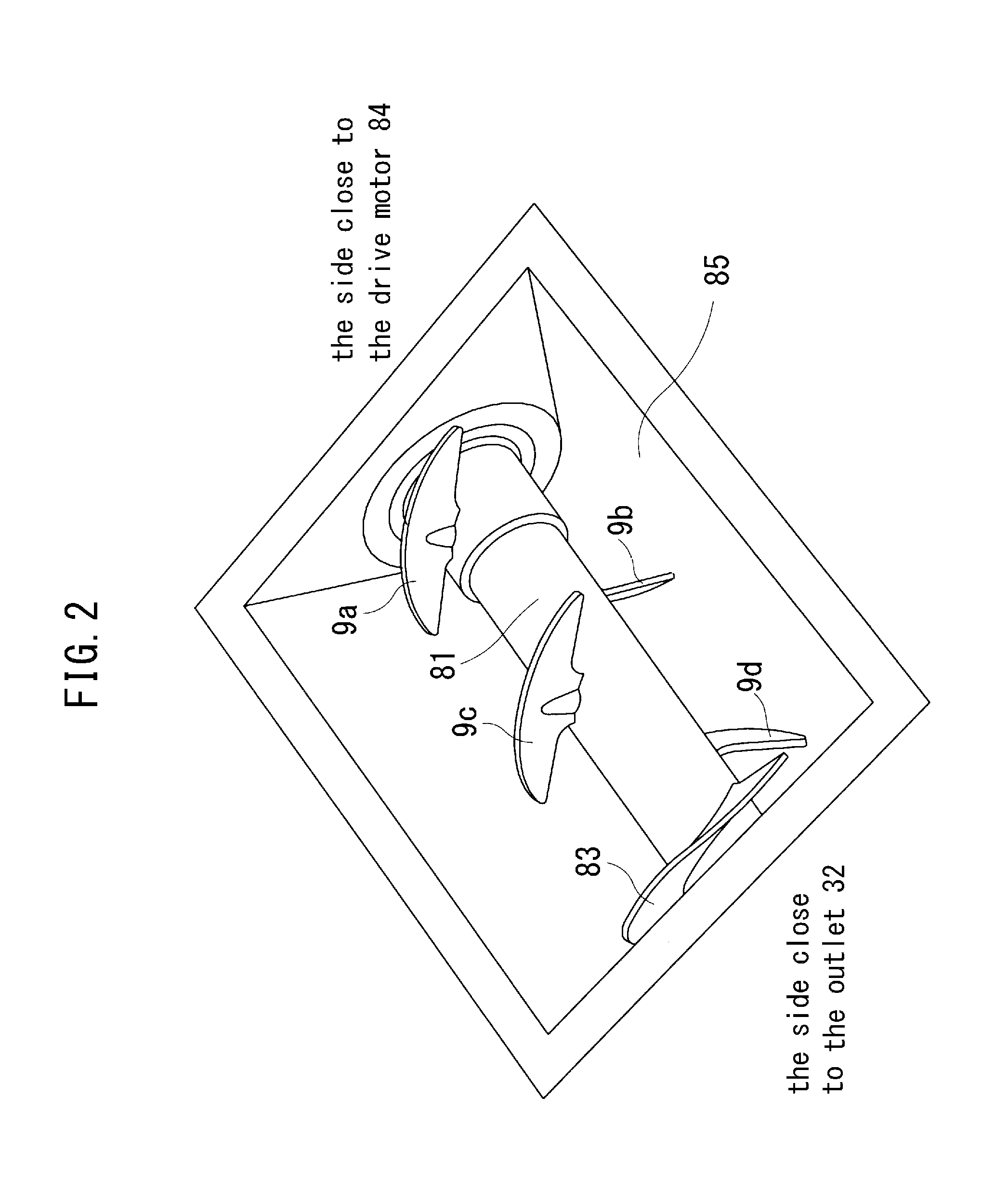
[0023]A powder / particulate material agitator 1 in one embodiment of the present invention (hereafter simply referred to as “agitator 1”) is described below with reference to FIGS. 1 through 5. The agitator 1 includes a vessel 4 provided between an upper power / particulate material supplier 2 and a lower powder / particulate material discharger 3 to hold therein the powder / particulate material to be stirred, a stirrer 7 provided in the vessel 4 to include a stirrer rotating shaft 5 (hereafter simply referred to as “rotating shaft”5) arranged in a horizontal direction and main paddles 6 fastened as agitating members to the rotating shaft 5, and a multi-feeder 8 provided in the powder / particulate material discharger 3 to have both forward and reverse rotations. The multi-feeder 8 has a discharger rotating shaft 81 (hereafter simply referred to as “rotating shaft”81) and auxiliary paddles 9 rotated integrally with the rotating shaft 81 and configured to have smaller dimensions than those o...


PUM

PropertyMeasurementUnit
Angleaaaaaaaaaa
Sizeaaaaaaaaaa
Heightaaaaaaaaaa

Abstract

An agitator 1 has a vessel 4 provided between an upper powder / particulate material supplier 2 and a lower powder / particulate material discharger 3 to hold therein powder / particulate material to be stirred. The agitator 1 also has a stirrer 7 provided in the vessel 4 to have a stirrer rotating shaft 5 arranged in a horizontal direction and main paddles 6 fastened to the rotating shaft 5, and a multi-feeder 8 provided in the powder / particulate material discharger 3 to have both forward rotation and reverse rotation. The multi-feeder 8 has a discharger rotating shaft 81 and small-size auxiliary paddles 9 integrally rotated with the rotating shaft 81 and designed to be smaller in size than the main paddles 6. In the state of stirring the powder / particulate material in the vessel 4 by means of the stirrer 7, the agitator 1 has stirring assist function during reverse rotation of the multi-feeder 8 to cause the auxiliary paddles 9 to stir up the powder / particulate material in the powder / particulate material discharger 3 and feed the powder / particulate material back into the vessel 4. The agitator 1 also has discharge function during forward rotation of the multi-feeder 8 to discharge the powder / particulate material out of the powder / particulate material discharger 3 and the vessel 4. This arrangement effectively prevents the powder / particulate material from being accumulated in any dead space, while reducing the total height of the powder / particulate material discharger of the agitator.

Description

TECHNICAL FIELD[0001]The present invention relates to a powder / particulate material agitator, and more specifically to a powder / particulate material agitator configured to prevent accumulation of powder / particulate material in any dead space.BACKGROUND ART[0002]A powder / particulate material blender 1 disclosed in Patent Literature 1 includes a vessel 5 provided to have a powder / particulate material supplier 2 and a powder / particulate material discharger 3 and configured to blend two or more different types of powder / particulate materials by means of paddles 4, a rotary valve 6 connected with the powder / particulate material discharger 3, and a gas-particulate mixture generator 7 configured to mix powder / particulate material discharged from the rotary valve 6 with a gas to generate a gas-particulate mixture. The powder / particulate material blender 1 has a two-way valve 8 provided downstream of the rotary valve 6, a return pipe 9 arranged to connect the gas-particulate mixture generato...

Claims


Application Information

Patent Timeline
IPC IPC(8): B01F15/02B01F7/04
CPCB01F3/18B01F7/00133B01F7/00158B01F7/00633B01F7/00708B01F15/0289B01F7/08B01F13/0032B01F13/1038B01F15/027B01F7/04B01F23/60B01F27/0723B01F27/0726B01F27/191B01F27/2123B01F27/70B01F27/72B01F33/5013B01F33/824B01F35/752B01F35/754551B01F35/71
Inventor KATO, FUMIO
Owner TSUKASA
Why Eureka
Try Eureka