
Distortion compensation circuit

a distortion compensation and circuit technology, applied in the direction of rf amplifiers, amplifiers with control circuits, amplifier modifications to reduce non-linear distortion, etc., can solve the problems of unfavorable distortion compensation and waste of resources

Inactive Publication Date: 2011-10-20
SUMITOMO ELECTRIC IND LTD
View PDF3 Cites 0 Cited by
  • Summary
  • Abstract
  • Description
  • Claims
  • Application Information

AI Technical Summary

Benefits of technology

[0007]It is an object of the present invention to provide a distortion compensation circuit that performs distortion compensation with further efficiency.
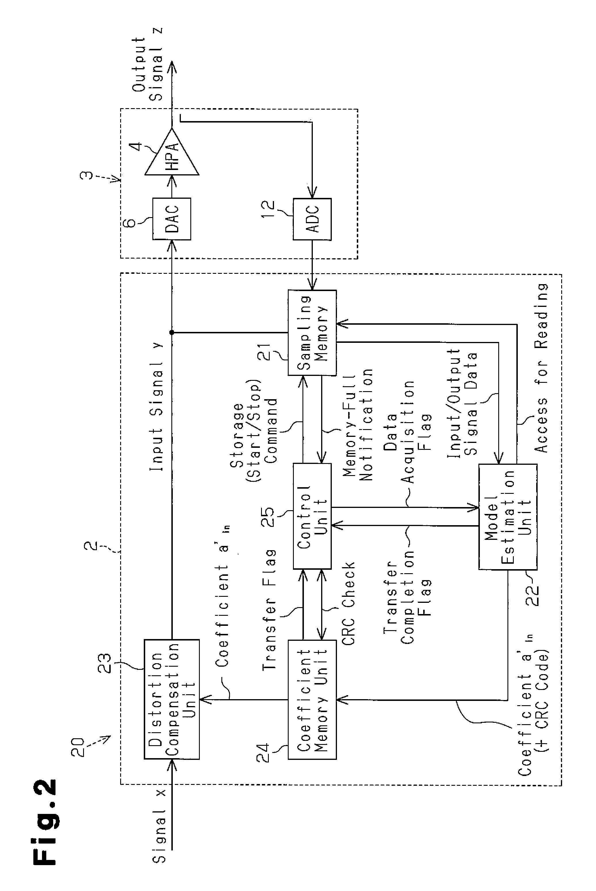
[0009]In the above-described distortion compensation circuit, the control unit stores the input signal and the output signal corresponding to a predetermine time in the memory unit and controls the memory unit to re-store the input signal and the output signal in order to obtain a new parameter after the distortion compensation unit performs distortion compensation with the parameter obtained from the input signal and the output signal stored in the memory unit. Thus, after the input signal and the output signal corresponding to the predetermined time is stored in the memory unit, the input and output signals of the amplifier are not stored in the memory unit until distortion compensation is performed (input and output signals reflecting distortion compensation performed with the parameter obtained from the input signal and output signal stored in the memory unit). Accordingly, the input and output signals stored in the memory unit reflects the effect of the distortion compensation based on the immediately previous input and output signals stored in the memory unit.
[0010]This prevents a situation in which the acquired input and output signals do not reflect the effect of the distortion compensation based on the immediately previous input and output signals like in the prior art. However, the above-described state prevents such a situation and performs distortion compensation with further efficiency.
[0012]In this case, the control unit easily recognizes that the input and output signals corresponding to the predetermined time are stored in the memory when the memory is in the memory full state. Further, the control unit easily controls the memory to stop the storage of the input and output signals with the memory 21.

Problems solved by technology

The conventional distortion compensation circuit has a problem in that such useless process is carried out and that distortion compensation is not efficiently performed.

Method used


Image

  • Distortion compensation circuit
  • Distortion compensation circuit
  • Distortion compensation circuit

Examples


Embodiment Construction

[0016]Embodiments of the present invention will now be described with reference to the drawings.

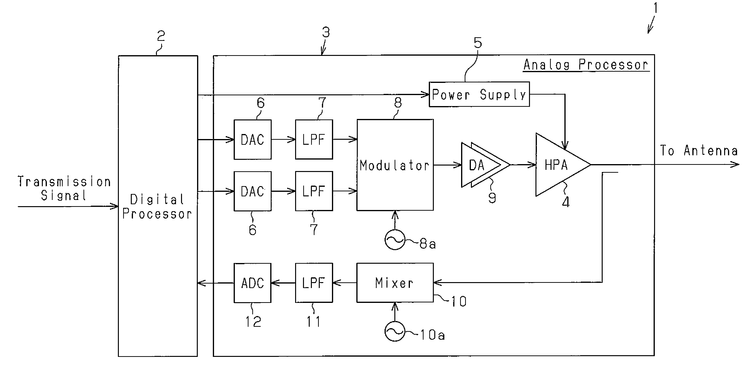
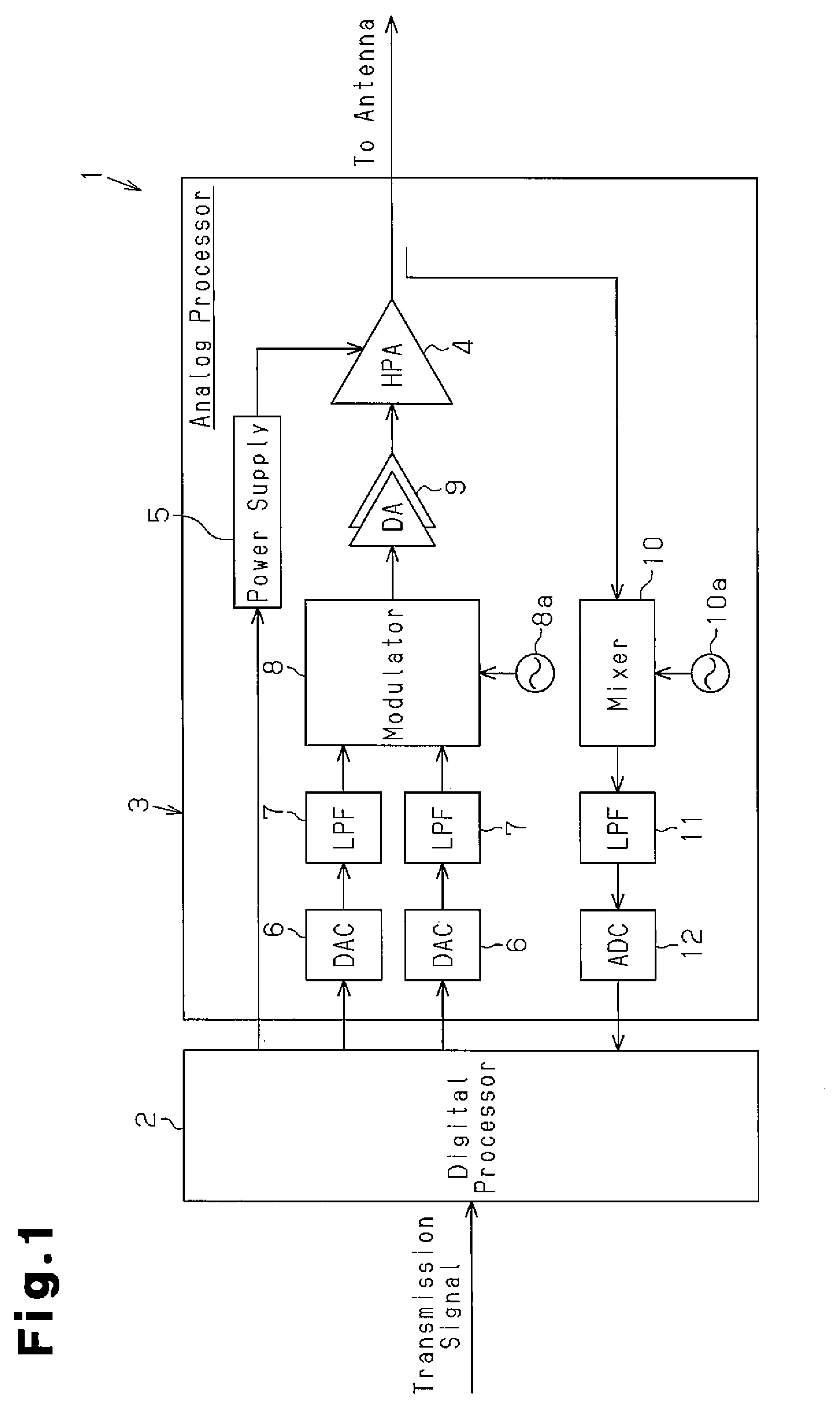
[0017]FIG. 1 is a circuit diagram showing the hardware structure of an amplifier device 1 incorporating a distortion compensation circuit according to the present invention. The amplifier device 1 amplifies a transmission signal of a wireless communication device or the like and includes a digital processor 2, which functionally includes a distortion compensation circuit, and an analog processor 3, which includes a high power amplifier (HPA, hereinafter, also referred to as amplifier) 4.

[0018]The digital processor 2 provides the analog processor 3 with a transmission signal serving as an input signal that is input to the amplifier 4, and acquires an output signal, which is output by the amplifier 4, from the analog processor 3.

[0019]The analog processor 3 includes a power supply 5, which supplies power supply voltage to the amplifier 4 in addition to a digital-to-analog (DA) converter (DA...


PUM


Abstract

Disclosed is a distortion compensation circuit that efficiently compensates for distortion. A distortion compensation circuit (20) comprises a sampling memory unit (21), which accumulates an input signal and an output signal from an amplifier (4), a model estimation unit (22), which reads the input and output signals that are accumulated upon the sampling memory unit (21), estimates a model that represents an input / output characteristic of the amplifier (4), and outputs a coefficient that denotes the model thus estimated, and a distortion compensation unit (23), which compensates for a distortion of the amplifier (4), based on the coefficient. The distortion compensation circuit (20) further comprises a control unit (25), which causes the accumulation of the input signal and the output signal upon the sampling memory unit (21) of a predetermined length, and controls the sampling memory unit (21) to accumulate the input and output signals anew in order to obtain a new coefficient after the distortion compensation is carried out by the distortion compensation unit (23) according to the coefficient that is obtained from the input and output signals that have been accumulated upon the memory unit.

Description

RELATED APPLICATIONS[0001]This application is the U.S. National Phase under 35 U.S.C. §371 of International Application No. PCT / JP2009 / 067036, filed on Sep. 30, 2009, which in turn claims the benefit of Japanese Application No. 2008-327917, filed on Dec. 24, 2008, the disclosures of which Applications are incorporated by reference herein.TECHNICAL FIELD[0002]The present invention relates to a distortion compensation circuit that functions to compensate for nonlinear characteristics of a high power amplifier used in a wireless transceiver.BACKGROUND ART[0003]A high output amplifier (HPA) having high efficiency generally has input / output characteristics with low linearity. When power is amplified using such amplifier, the desired output may not be obtained due to distortion of input / output characteristics. Thus, in order to compensate for the distortion of the amplifier, a distortion compensation circuit that obtains the desired amplifier output by performing a distortion compensation...

Claims


Application Information

Patent Timeline
IPC IPC(8): H03F1/26
CPCH03F1/3247H03F1/3258H03F3/24H03F2201/3233H03F2200/451H03F2201/3212H03F2200/336H03F1/32
Inventor ONISHI, MASAHIKOILLARIONOV, MIKHAIL
Owner SUMITOMO ELECTRIC IND LTD
Learn More