
Power generator with high power-to-volume ratio

a power generator and high-power technology, applied in the direction of electrical equipment, mechanical energy handling, dynamo-electric machines, etc., can solve the problems of low power-to-volume ratio, low magnetic permeability, and high cost of current available large-scale wind turbines when combined with direct-drive power generators. , to achieve the effect of high power-to-volume ratio, low magnetic permeability, and high magnetic permeability

Inactive Publication Date: 2011-10-20
HOULY
View PDF7 Cites 9 Cited by
  • Summary
  • Abstract
  • Description
  • Claims
  • Application Information

AI Technical Summary

Benefits of technology

[0007]The primary objective of the present invention is to provide a power generator with high power-to-volume ratio, whereby with the same moving speed or rotational speed of prime mover, the generator of the present invention can provide a much greater power output per unit volume than the conventional power generators.
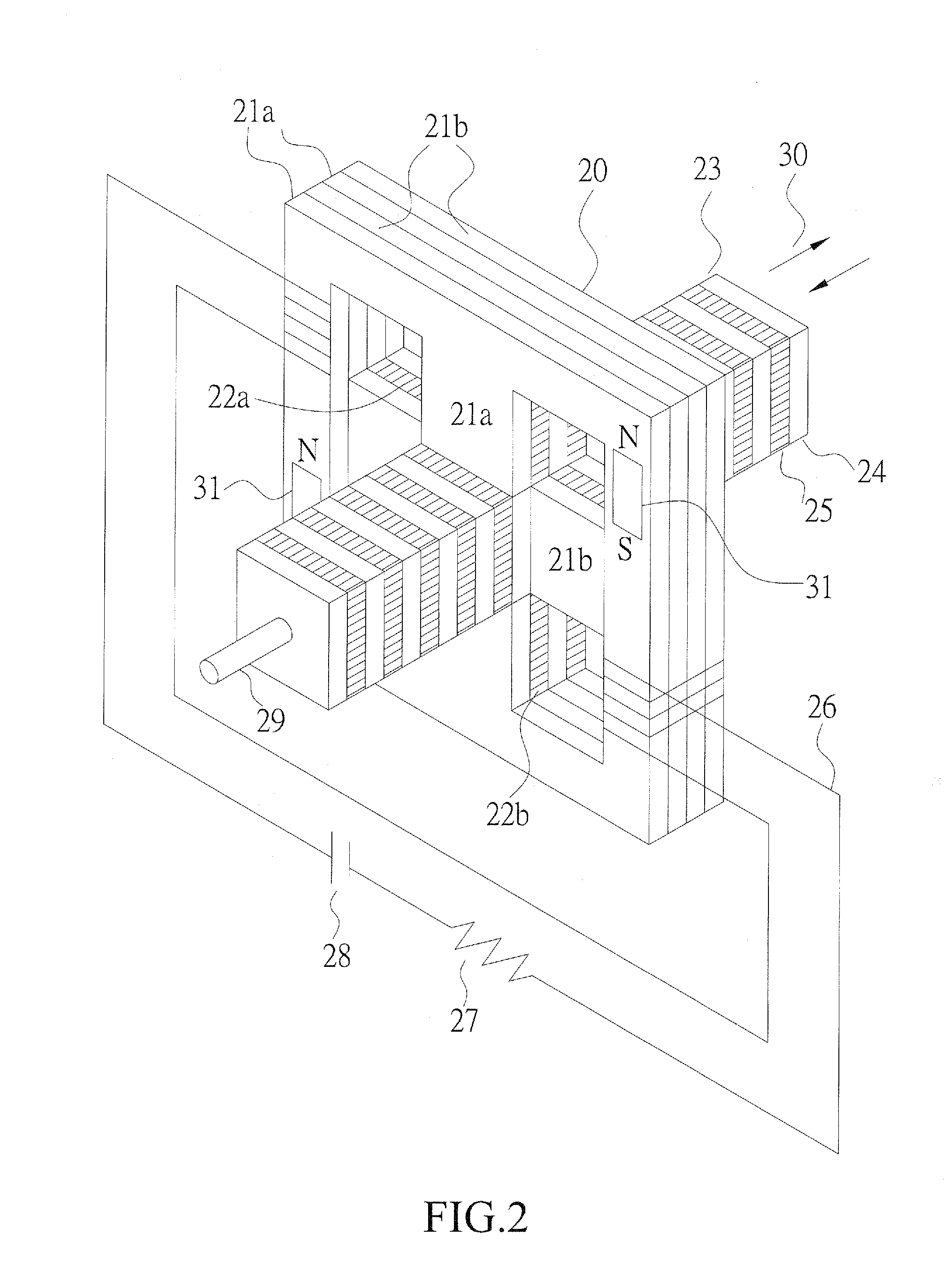
[0011]In the previously mentioned power generator with high power-to-volume ratio, the magnetic flux in the magnetic path can be generated by a permanent magnet or through external excitation or self-excitation, or alternatively, a combination of permanent magnet and self-excitation, or combined excitation of self-excitation and external excitation can be adopted. The permanent magnet is embedded in the silicon steel plates of stator. The external excitation is provided by supplying an external DC power through an excitation coil to generate magnetic flux. The self-excitation is realized through generation of power by the residual magnetism, in the stator and then is subjected to rectification of output power to supply a direct current to an excitation coil to generate more magnetic flux. The combination of permanent magnet and self-excitation is to generate power with the magnetic flux of the permanent magnet and then inducing self-excitation to generate an even greater magnitude of magnetic flux. The combination of external excitation and self-excitation is to use an external DC power source to carry out magnetic excitation and thus applying the self-excitation to generate a great magnetic flux. Both circuits must be added with a diode to prevent shorting.
[0012]In the previously mentioned power generator with high power-to-volume ratio, the silicon steel plates can be replaced by other materials of high magnetic permeability and the plastic plates can be replaced by other materials of low magnetic permeability. The silicon steel plates are formed by stacking multiple this sheets in order to reduce eddy current loss.
[0013]In the previously mentioned power generator with high power-to-volume ratio, the mover or the rotor carries no coil, conductor, or permanent magnet thereon. This is on the contrary to the known synchronous generators, induction generators, and direct current generators, of which the rotor carries a coil, conductor; or permanent magnet. As a result, the present invention is easy to manufacture and is structurally tough. Increasing the power-to-volume ratio means reduces the consumption of material, so that the present invention can reduce cost as compared to the conventional power generators.

Problems solved by technology

The power generator has been produced for more than one century, the theory and technology of the power generator got mature before half a century and in other words, they have not been significantly improved for almost fifty years.
The currently available large scale wind turbines, when combined with a direct drive power generator, will become bulky and expensive.
However, the gear box is generally very heavy and expensive and this is one of the reasons that the cost of wind power generator cannot compete with the traditional power generation.
Sea wave power generation is for the time being not put into practical commercial operation due to lacking of available linear motion generator of sufficient efficiency.
As to a Stirling engine that is fit for solar power generation, it also suffers bulkiness of linear power generator and is thus impractical.

Method used


Image

  • Power generator with high power-to-volume ratio
  • Power generator with high power-to-volume ratio
  • Power generator with high power-to-volume ratio

Examples


Embodiment Construction

[0028]The following descriptions are exemplary embodiments only, and are not intended to limit the scope, applicability or configuration of the invention in any way. Rather, the following description provides a convenient illustration for implementing exemplary embodiments of the invention. Various changes to the described embodiments may be made in the function and arrangement of the elements described without departing from the scope of the invention as set forth in the appended claims.

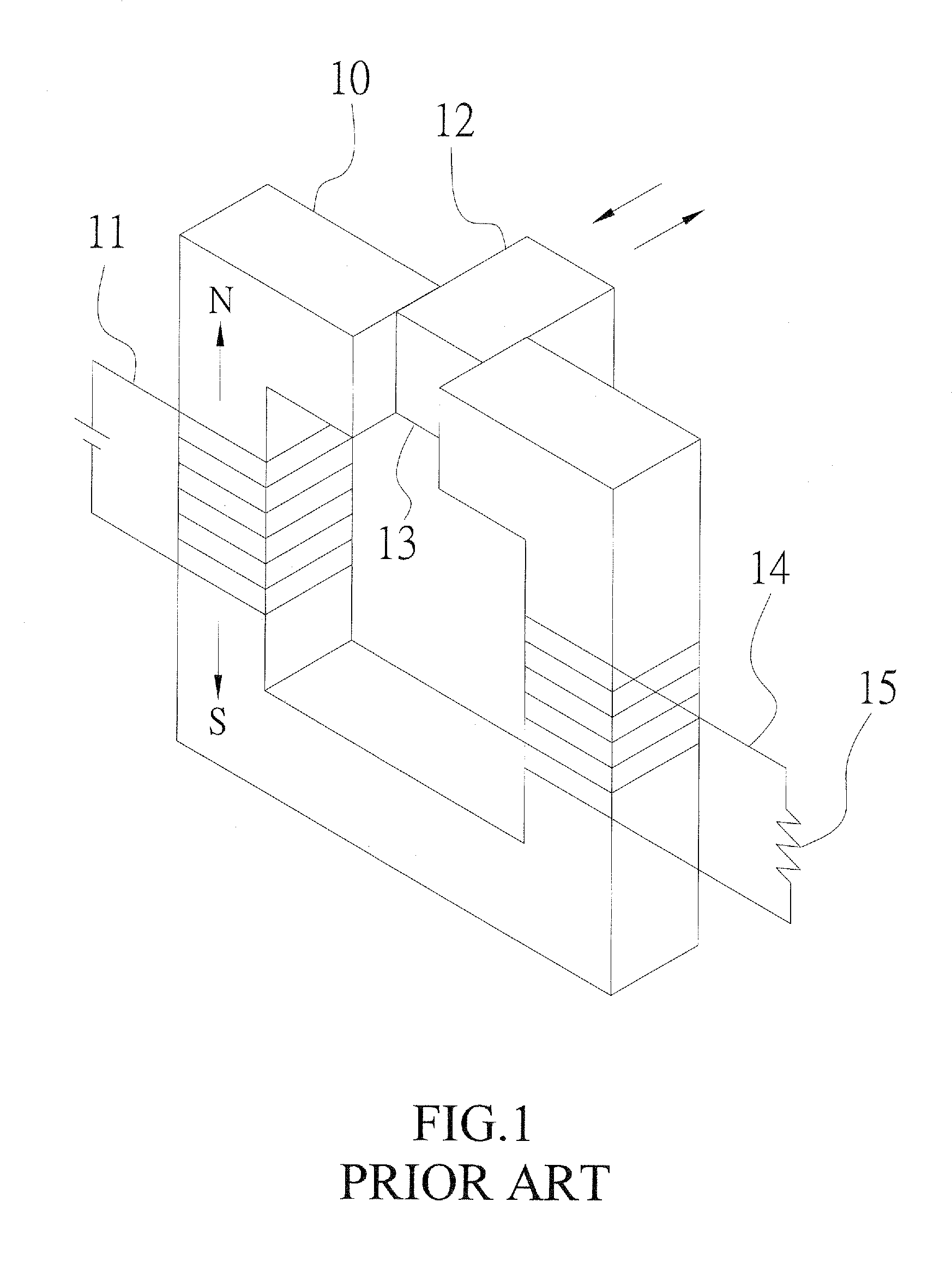
[0029]Referring to FIG. 1, the structure of a conventional linear mover generator is shown. As shown, a stator 10 is made for example silicon steel plates that usually using in transformer. An exciter 11 comprises a direct current (DC) power source and a winding to generate magnetic flux (y) that induces a north (N) pole and a south (S) pole in the stator 10. Alternatively, a permanent magnet can be instead or combined with the stator 10 to generate magnetic flux in the stator 10. A mover 12 is allo...


PUM


Abstract

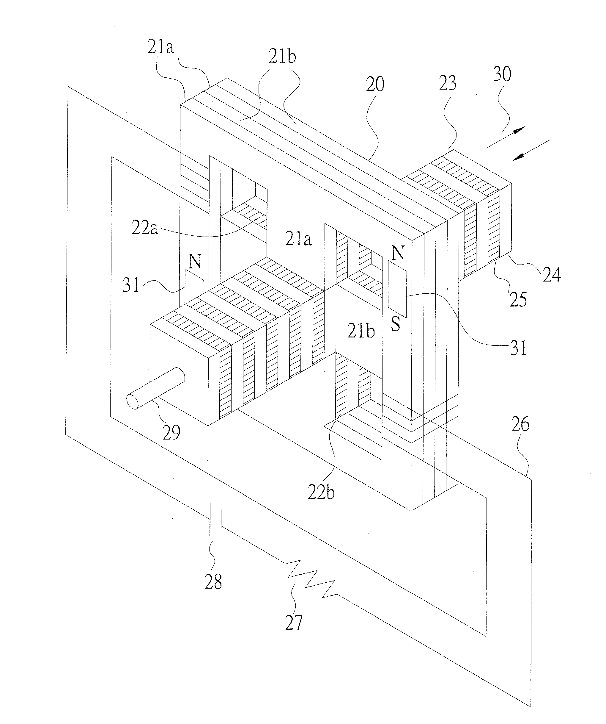
A power generator with high power-to-volume ratio includes a plurality of silicon steel plates and air gaps or plastic plates, which are alternately arranged to form adjacent magnetic paths of a stator and a mover or a rotor of a power generator and which have intervals (which are defined by thickness or width of the silicon steel plates or the air gaps or the plastic plates) that are set to be very small, whereby when the mover or the rotor take a movement or rotation by one interval, magnetic flux induced in a magnetic path of the stator around which an induction coil is wound changes magnitude and direction thereof so that through quick changes, the induction coil induces a higher voltage and thus significantly increases power-to-volume ratio of the generator.

Description

(a) TECHNICAL FIELD OF THE INVENTION[0001]The present invention generally relates to a power generator with high power-to-volume ratio, and more particularly to a power generator with high power-to-volume ratio that makes fast change of the magnitude and direction of magnetic flux in a magnetic path in order to induce a higher voltage in an induction coil of a stationary magnetic path (namely a stator) so that the power generator can significantly increases the capacity of output power when compared to a conventional power generator of the same volume with a movable magnetic path, which is a mover or a rotor, moving in the same moving speed or rotational speed.(b) DESCRIPTION OF THE PRIOR ART[0002]A power generator employs an operation principle originating from a natural phenomenon, which shows that a conductor moving in a magnetic field may generate an induction voltage by following the formula: E=NBlV, where E is electrical voltage, B is magnetic flux density, l is the length of ...

Claims


Application Information

Patent Timeline
Patent Type & Authority Applications(United States)
IPC IPC(8): H02K41/03
CPCH02K7/1869H02K41/03H02K35/06
Inventor LIU, KUO-SHEN
Owner HOULY
Learn More