
Suction type bottle cap

a bottle cap and suction technology, applied in the field of bottle caps, can solve the problems of inaccurate pouring amount, waste of liquid, and unnecessary waste, and achieve the effects of reducing the possibility of air suction, facilitating measuring of sucked liquid, and facilitating suction and discharging

Inactive Publication Date: 2011-10-20
CHEN ZHIQIU +2
View PDF8 Cites 0 Cited by
  • Summary
  • Abstract
  • Description
  • Claims
  • Application Information

AI Technical Summary

Benefits of technology

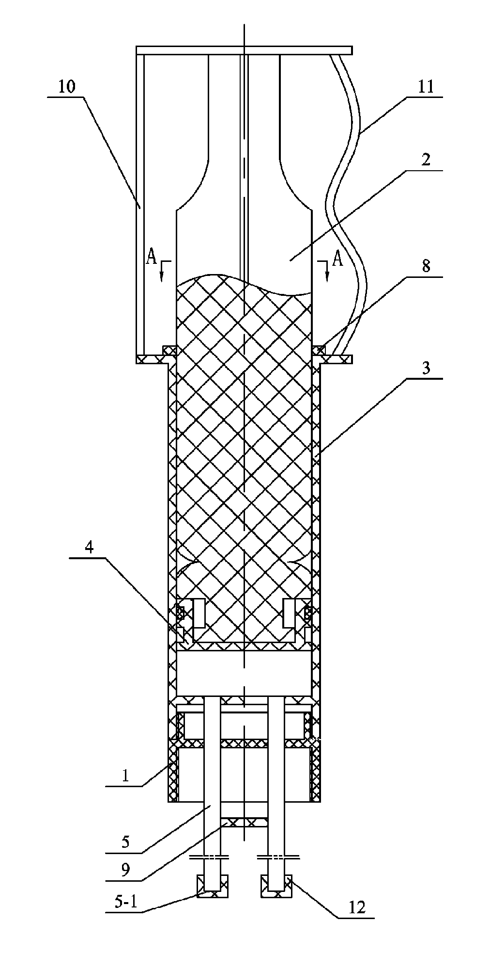
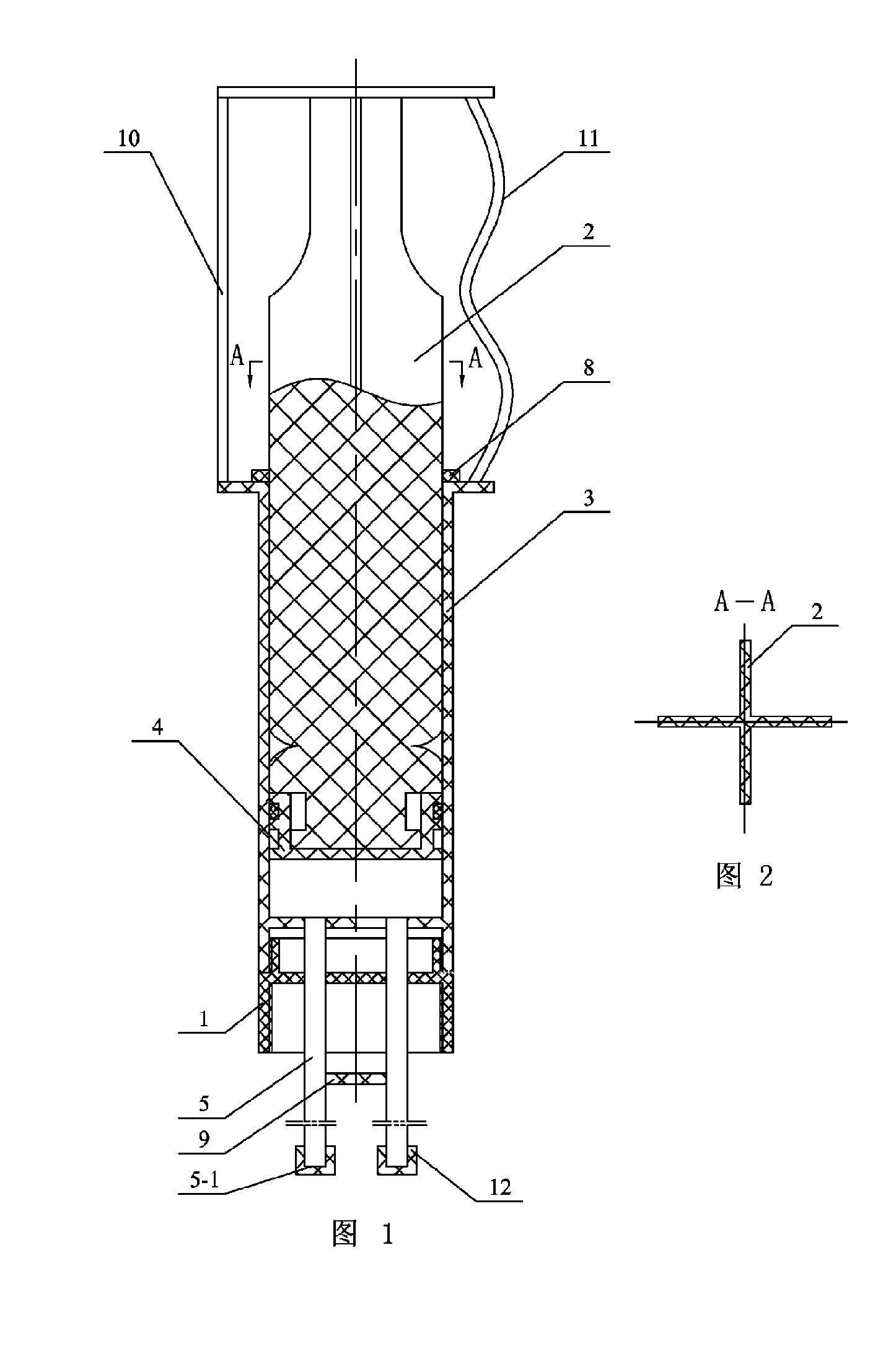
Technical proposal II: on the basis of the technical proposal I, the inner wall or the outer wall of the liquid suction cavity 3 is provided with a scale mark. And with such an arrangement, the measurement for the sucked liquid is facilitated.
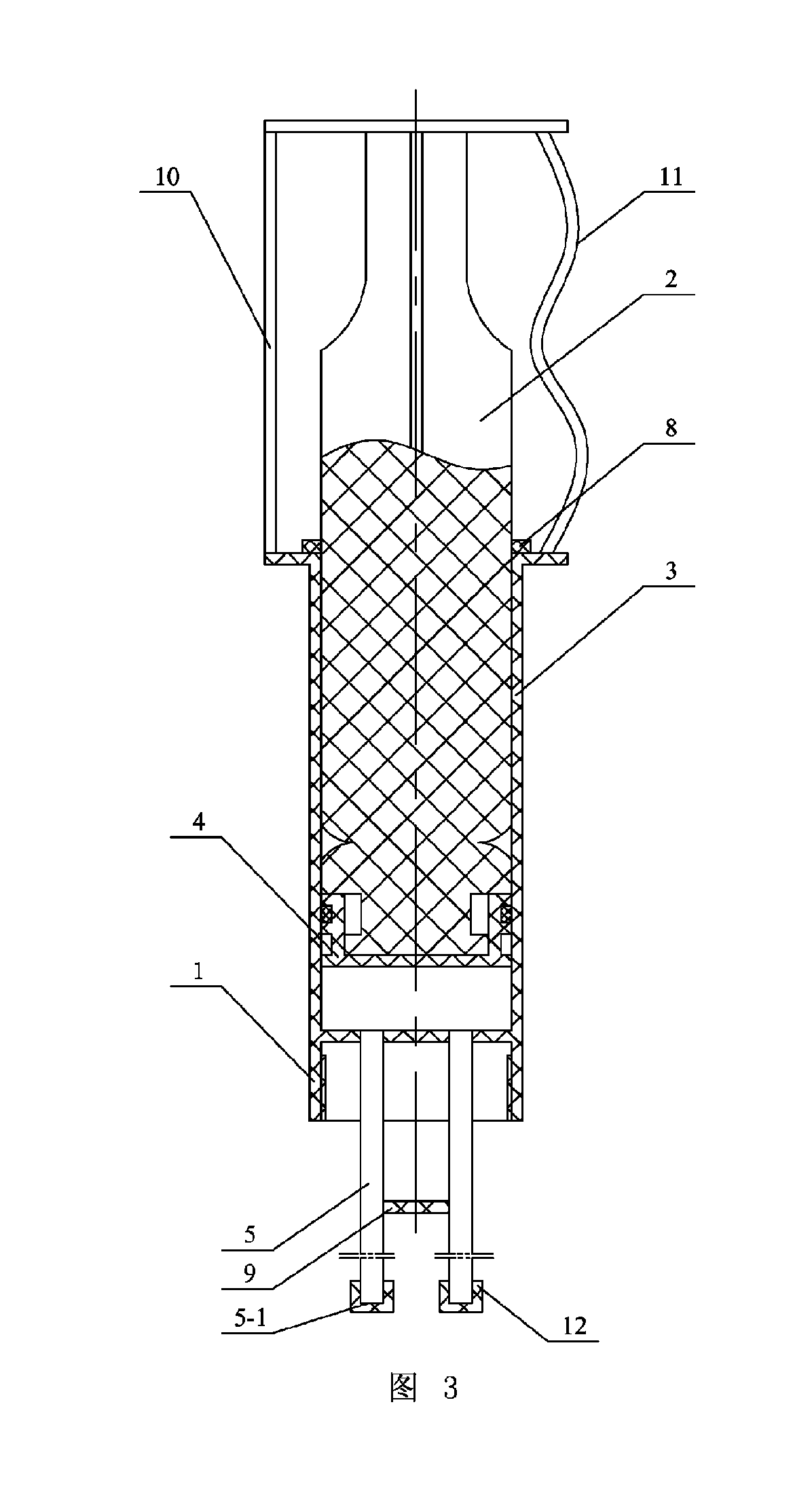
Technical proposal III: on the basis of the technical proposal I or II, the number of the suction pipe is 1 to 4, the suction pipe mouth is a plane or a slope, and the suction pipe 5 is straight or curved. And with such an arrangement, faster suction and discharging can be obtained when a plurality of suction pipes 5, instead of one suction pipe 5, are adopted. When a plurality of suction pipes 5 are arranged, the suction pipes 5 may be arranged on the same plane as the suction pipe month 5-1, but should be arranged to form a slope with respect to the suction pipe month 5-1 as much as possible, so that, when the bottle body is sloped to suck the liquid, a plurality of suction pipe months come into parallel contact with the wall of the bottle and are all submerged in the liquid as much as possible, not in the air above the liquid, therefore, the possibility of air suction is reduced.

Problems solved by technology

In order to take out the liquid in current liquid-accommodating bottles, the liquid could flow from the inner side to the outer side of bottle mouth to pollute bottle nozzle or flow to the outer wall of the bottle when the liquid in the bottle is poured and the bottle is placed vertically after the liquid is poured, thereby causing unnecessary waste and pollution, and this situation gets worse if the viscosity of the liquid is larger.
In addition, as the bottle for accommodating liquid has no scale mark, the manufacturers that produce the above liquids fail to introduce the usage amounts of the liquid under different circumstances to consumers through convenient and definite measurement scale values so as not to give consumers the usage guidance, and the pouring amount is usually determined according to individual experience during pouring, so inaccurate pouring amount is caused.
And in case of excessive pouring, the liquid cannot be returned.

Method used


Image

  • Suction type bottle cap
  • Suction type bottle cap
  • Suction type bottle cap

Examples


embodiment 1

Description is made below to the embodiment with reference to FIGS. 1, 3 to 5, 7, 8, 9, 10, 11 and 12; the suction type bottle cap in the embodiment comprises a bottle cap 1, the sidewall of an inner cavity of the bottle cap 1 is provided with an internal thread connected with a bottle mouth; the suction type bottle cap further comprises a suction device; the suction device comprises a vacuum draw bar 2, a liquid suction cavity 3, a piston 4 and at least one suction pipe 5; the liquid suction cavity 3 is connected with the bottle cap 1, the upper end of the suction pipe 5 is communicated with the liquid suction cavity 3, the lower end of the vacuum draw bar 2 is mounted in the liquid suction cavity 3 and the lower end of the vacuum draw bar 2 is equipped with the piston 4.

The suction type bottle cap in the embodiment is better in practicability and is more suitable for popularization and application.

When the length of the suction pipe 5, which can be any length, is less than a half ...

embodiment 2

The difference of the embodiment from Embodiment 1 is that: the upper end of the suction pipe 5 penetrates through the bottle cap 1 to be communicated with the liquid suction cavity 3.

When the length of the suction pipe 5, which can be any length, is less than a half of the height of a bottle (or no more than 10 centimeters), the liquid at the lower part of the bottle can be sucked by the suction pipe even if the suction pipe is located at the upper part of the bottle. When in use, the liquid can be sucked only by the steps of sloping the bottle to cause the liquid to flow to the position near the bottle mouth and then stretching the suction pipe 5 to the position in the liquid mouth where the liquid exists. Preferably, in order to suck the liquid more conveniently, the suction pipe can be designed to be slantwise, curved or folded in relation to the bottle, thus the suction pipe mouth gets close to the bottle wall near the bottle mouth more easily. The liquid is sucked into the liq...

embodiment 3

Description is made below to the embodiment with reference to FIGS. 1, 3 to 5, 7 and 8; the difference of the embodiment from Embodiment 2 or 3 is that: the liquid suction cavity 3 and the bottle cap 1 are integrated or split in two parts, the liquid suction cavity 3 and the bottle cap 1, which are split in two parts, are tightly connected with each other in the manner of a threaded fastener, and the integration of the liquid suction cavity 3 with the bottle cap 1 is convenient for processing.


PUM


Abstract

A suction type bottle cap has a bottle cap and a suction device. The suction device comprises a vacuum draw bar, a liquid suction cavity, a piston and at least one suction pipe (5). The liquid suction cavity is connected with the bottle cap, the upper end of the suction pipe communicates with the liquid suction cavity, the lower end of the vacuum draw bar is placed in the liquid suction cavity, and the piston is arranged at the lower end of the draw bar. The suction type bottle cap can prevent liquid from polluting the bottle mouth so as to avoid unnecessary waste, is convenient for liquid suction and accurate in measurement, and is suitable for the suction of various liquids.

Description

TECHNICAL FIELDThe invention relates to a bottle cap.BACKGROUND ARTIn order to take out the liquid in current liquid-accommodating bottles, the liquid could flow from the inner side to the outer side of bottle mouth to pollute bottle nozzle or flow to the outer wall of the bottle when the liquid in the bottle is poured and the bottle is placed vertically after the liquid is poured, thereby causing unnecessary waste and pollution, and this situation gets worse if the viscosity of the liquid is larger. For example: edible oil, shampoo, soy sauce, vinegar, detergent and the like, one drop at least or multiple drops of them at most flow out of the bottle mouth when the liquid in the bottle is poured and the bottle is placed vertically after the liquid is poured. In addition, as the bottle for accommodating liquid has no scale mark, the manufacturers that produce the above liquids fail to introduce the usage amounts of the liquid under different circumstances to consumers through conveni...

Claims


Application Information

Patent Timeline
Patent Type & Authority Applications(United States)
IPC IPC(8): B65D41/00
CPCA45D34/00A45D2200/056A45D2200/052
Inventor CHEN, YUXIANG
Owner CHEN ZHIQIU
Learn More