Brake Beam Assembly

a technology for brake beams and assemblies, which is applied in the direction of rail brake actuation, rail braking systems, railway components, etc., can solve the problems of brake head failure, damage to the brake head or other components of the brake beam assembly, and the brake head is prone to significant fatigue, etc., to achieve high static strength and fatigue resistance, low cost, and low weight

Active Publication Date: 2011-10-20
A STUCKI CO
View PDF6 Cites 12 Cited by
  • Summary
  • Abstract
  • Description
  • Claims
  • Application Information

AI Technical Summary

Benefits of technology

[0028]It is another object of the present invention to provide an embodiment of a brake beam assembly of the above referred nature which has high static strength and fatigue resistance while maintaining a low weight and a low cost.
[0029]It is a further object of the present invention to provide an embodiment of a brake beam assembly in which it is possible to replace the brake heads without harming, effecting or disassembling other components thereof and without disconnecting the brake beam assembly from the truck of a railway car to which the brake beam assembly is mounted.

Problems solved by technology

Although it is mentioned that the above referenced brake beam designs provide adequate high static strength and fatigue resistance, the end extension and brake head are formed as a single piece, which may be problematic when the brake head has to be replaced.
Furthermore, since all of the pressure from the breaking action and the forces derived from maintaining the brake beam in place are concentrated in the brake head component, which has an integral extension component, the brake heads are prone to experience significant fatigue, which may damage the brake head or other components of the brake beam assembly.
Such fatigue may also cause the brake head to fail.

Method used


Image

  • Brake Beam Assembly
  • Brake Beam Assembly
  • Brake Beam Assembly

Examples


Embodiment Construction

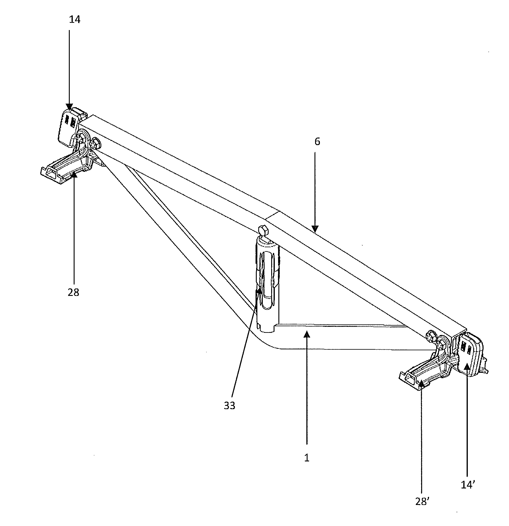
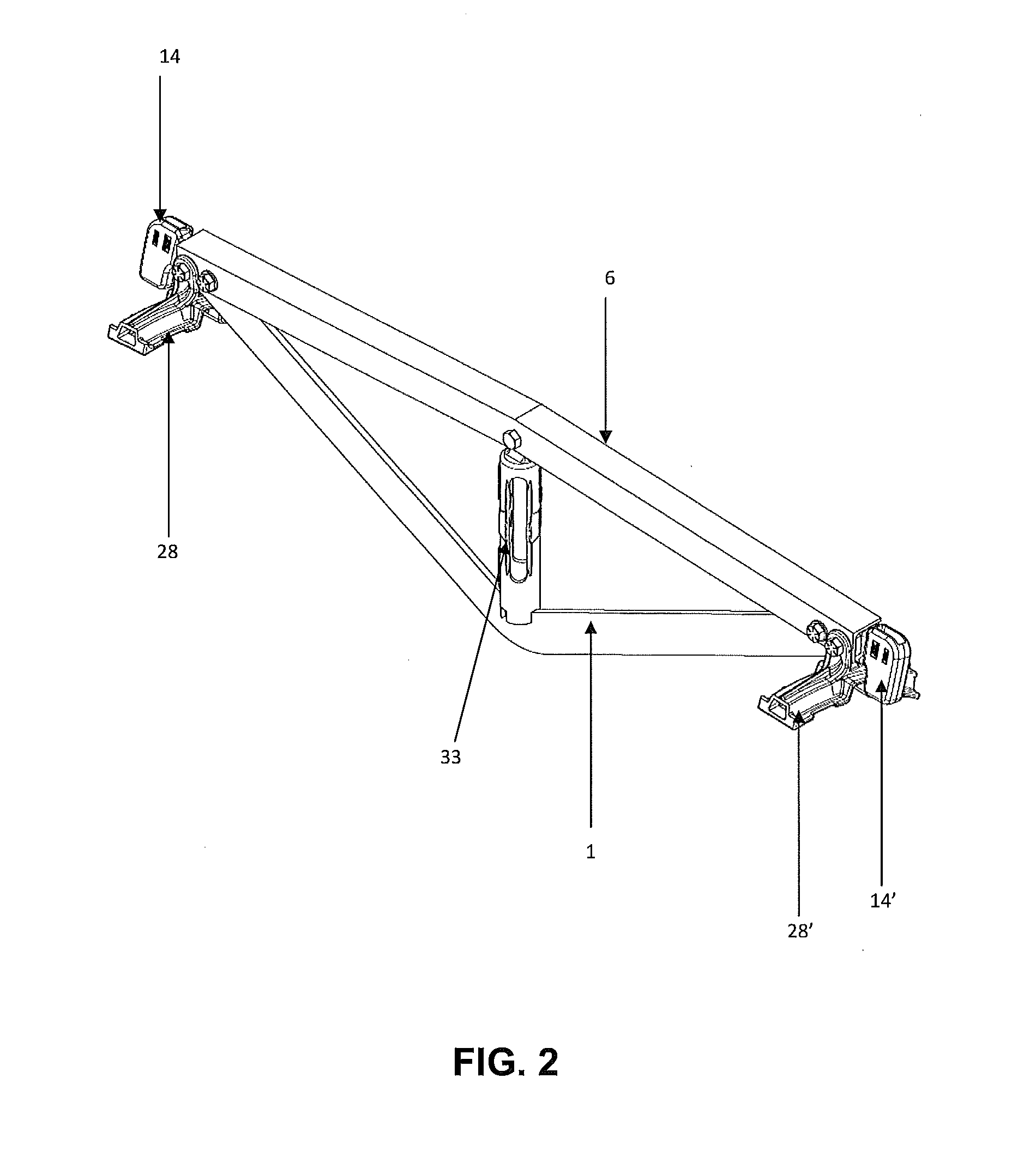
[0045]Referring to FIGS. 1-14, an embodiment of the inventive brake beam assembly includes a generally flat, V-shaped tension member 1, a compression member 6 and a strut, or fulcrum, 33 positioned between the tension member 1 and compression member 6. A pair of brake heads 28, 28′ are attached at opposite ends of the brake beam assembly. Each end of the compression member may be attached to a respective end of the tension member 1 within a cavity 29 of the brake head 28, 28′.

[0046]As shown more clearly in FIGS. 4-5, the generally V-shaped tension member 1 has a first end portion 2 and a second end portion 3. The first end portion 2 includes a first hole 4 and a second hole 5. The second end portion 3 includes a first hole 4′ and a second hole 5′. The holes 4, 5, 4′ and 5′ may be formed in the tension member 1 such that the holes are contiguous with the tension member 1. The tension member 1 is preferably flat having a generally rectangular cross-section, and includes a first surfac...


PUM


Abstract

A low weight and low cost brake beam assembly having high static strength and fatigue resistance having two independent brake heads each including a receiving section for receiving and retaining an end of a tension member, an end of a compression member and a portion of an end extension.

Description

FIELD OF THE INVENTION[0001]The present invention is directed toward brake beams for railway cars and, more particularly, toward a low weight and low cost brake beam assembly having high static strength, fatigue resistance, replacement ability of wear components.BACKGROUND OF THE INVENTION[0002]There are well known brake heads assemblies for railway cars by which a brake shoe is pressed against a wheel in order to decrease or stop the rotational speed of the wheel and of the railway car for braking. The brake heads are typically actuated by a pneumatic actuation system.[0003]Generally, a structure called a “brake beam” is mounted transversely in the bogie of a railway car and is linked to a lever, which applies a force in order to press a brake shoe of a brake head against a wheel to apply a braking force to the wheel. Often, the brake beam has two ends and each end is attached to a respective break head. Examples of brake beam assemblies may be appreciated from U.S. Pat. Nos. 2,170...

Claims


Application Information

Patent Timeline
Patent Type & Authority Applications(United States)
IPC IPC(8): B61H13/36
CPCB61H13/36
Inventor DE LA FUENTE FARIAS, JORGE ALBERTO
Owner A STUCKI CO
Why Eureka
Try Eureka