
Arc welding method and arc welding apparatus

Inactive Publication Date: 2011-10-13
DENSO CORP
View PDF7 Cites 35 Cited by
  • Summary
  • Abstract
  • Description
  • Claims
  • Application Information

AI Technical Summary

Benefits of technology

The present invention has been made in light of the problems set forth above and has as its object to provide an arc welding method and an arc welding apparatus, which are able to suppress generation of arc as much as possible when a metallic material containing oxygen is used as base metal, prevent burn-through of a weld portion, and make the shapes of joints at the weld portions more uniform than in the conventional art.
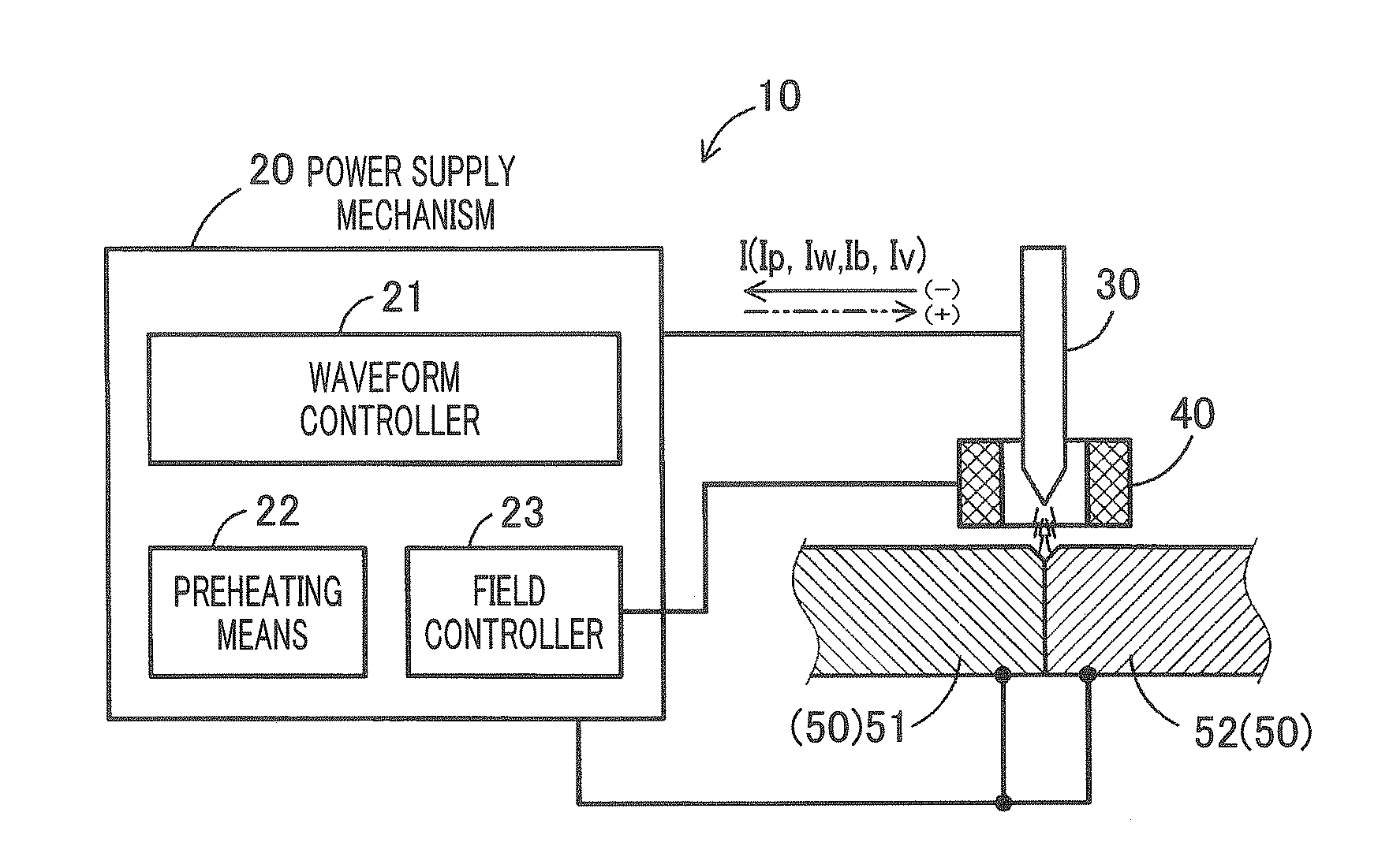
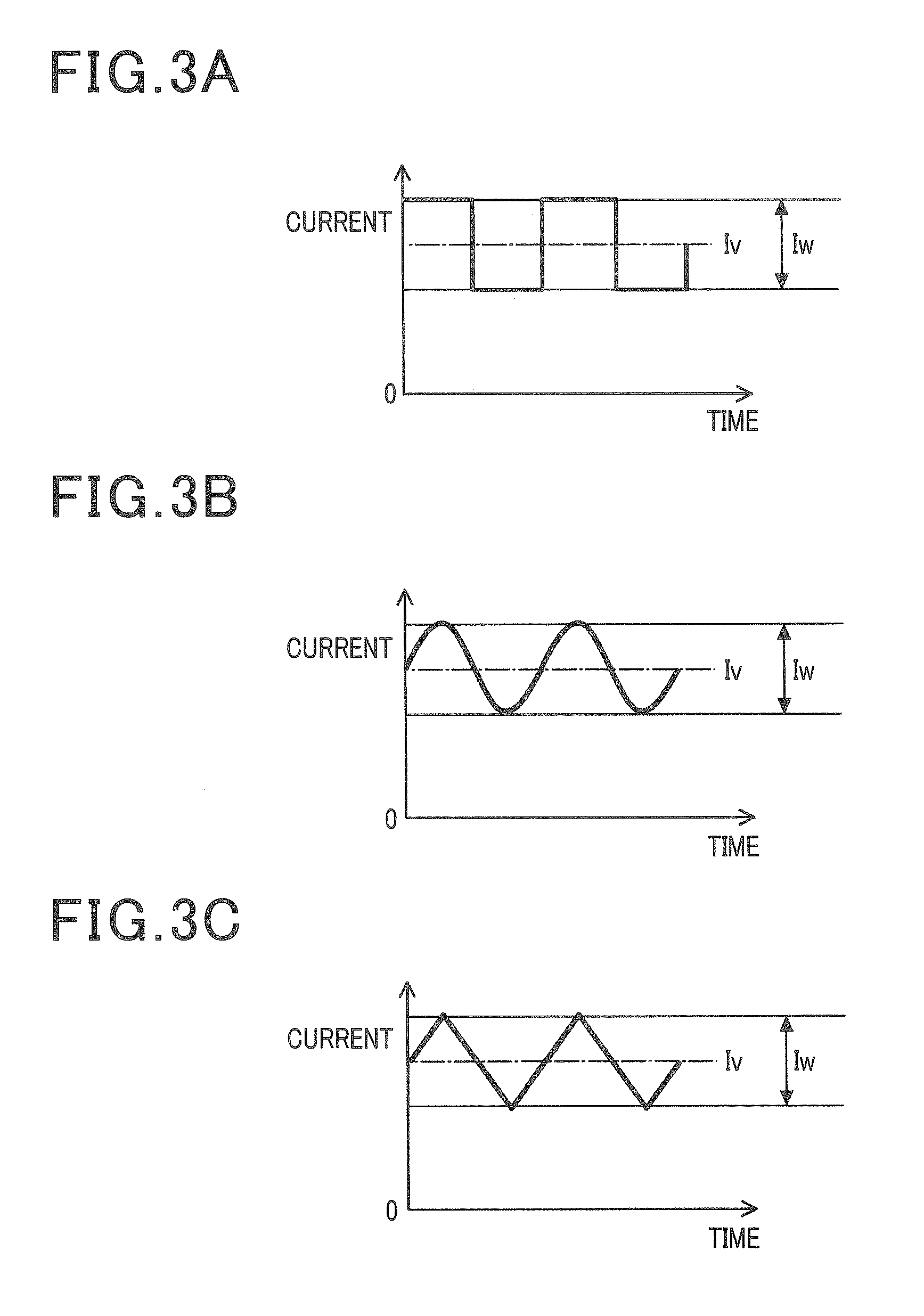
According to this aspect, the base metal is entirely or partially preheated by the preheating means. Therefore, the time frame for generating arc can be shortened, which arc is required for melting the base metal. Also, the waveform controller changes waveform between the peak current and the base current. Therefore, arc is generated only in one direction to thereby stabilize the generation pathway of arc. Further, the field controller changes the generation pathway of arc with the change of the magnetic field. Therefore, the molten metal pushed aside by the arc force is restored because the arc force is weakened with the change of the generation pathway. Accordingly, each weld portion is prevented from being burned through and the shapes of joints of the weld portions can be more uniform than in the conventional art.

Problems solved by technology

On the other hand, if the current ratio is larger than 2.0, the arc force will be so large that the weld portion is likely to be burned through.

Method used


Image

  • Arc welding method and arc welding apparatus
  • Arc welding method and arc welding apparatus
  • Arc welding method and arc welding apparatus

Examples


Embodiment Construction

With reference to the accompanying drawings, hereinafter will be described an embodiment of the present invention. It should be appreciated that, throughout the specification, the term “connect” or “connection” refers to “electrically connected” or “electrical connection” unless specifically defined. Also, the terms which indicate directions, such as top, down, left and right, which are given in the specification, refer to the directions with reference to the drawings as viewed.

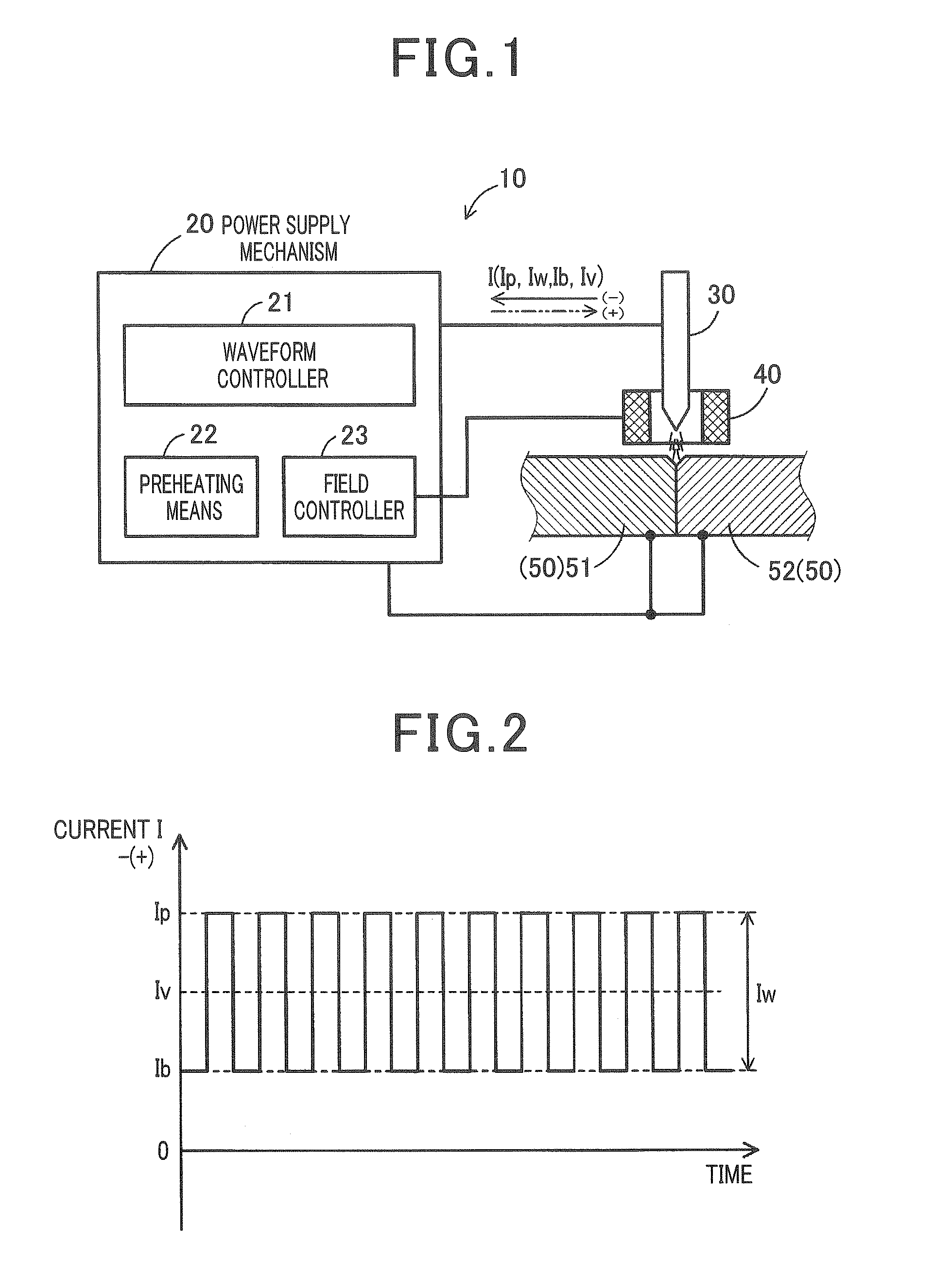
With reference to FIGS. 1 to 7, an arc welding apparatus according to an embodiment of the present invention will now be described.

FIG. 1 is a schematic diagram illustrating a configurational example of an arc welding apparatus 10 according to the embodiment. In the present embodiment, the arc welding apparatus 10 is provided as an apparatus for a TIG (tungsten inert gas) welding apparatus or a plasma arc welding apparatus. The arc welding apparatus 10 shown in FIG. 1 includes base metal 50 (i.e. first base m...


PUM

PropertyMeasurementUnit
Fractionaaaaaaaaaa
Frequencyaaaaaaaaaa
Frequencyaaaaaaaaaa

Abstract

A base metal composed of a plurality of metallic materials having an oxygen content of 10 ppm is first preheated partly or overall. Then AC (alternating current) current is made to pass through the preheated base metal and an electrode so as to generate an arc for welding the metallic materials. The waveform of the current is changed with time between a peak current value and a base current value excluding a current of zero value only in one of plus and minus polarity sides of the current. A current ratio defined by dividing a current amplitude between the peak and base current values by a current average of the alternating current is a range of 0.5 to 2.0. The alternating current has a frequency of 500 Hz or higher.

Description

CROSS-REFERENCE TO RELATED APPLICATIONThis application is based on and claims the benefit of priority from earlier Japanese Patent Application No. 2010-088500 filed Apr. 7, 2010, the description of which is incorporated herein by reference.BACKGROUND OF THE INVENTION1. Technical Field of the InventionThe present invention relates to an arc welding method in which an arc is generated between a base metal composed of metallic materials and an electrode to weld the metallic materials with each other, and to an arc welding apparatus which is capable of performing such welding work.2. Related ArtArc welding methods have been known. For example, JP-A-2001-054263 discloses a technique of arc welding method using TIG (tungsten inert gas) welding in which an arc is generated from a tungsten rod having a very high melting point toward a base metal to melt the base metal with the heat.Also, JP-B-3948767, for example, discloses a technique of controlling the current waveform or voltage of high-...

Claims


Application Information

Patent Timeline
IPC IPC(8): B23K9/10
CPCB23K9/092B23K2203/12B23K2203/10B23K9/23B23K2103/10B23K2103/12
Inventor TAKEDA, HIROAKIMORIGUCHI, KEIGONISHIO, SHIGEISA
Owner DENSO CORP
Learn More