
Apparatus and method for sealing tubeless tires

a tubeless tire and apparatus technology, applied in the field of sealing apparatus, can solve problems such as difficulty in establishing initial seals

Inactive Publication Date: 2011-10-13
BOSCH AUTOMOTIVE SERVICE SOLUTIONS
View PDF4 Cites 11 Cited by
  • Summary
  • Abstract
  • Description
  • Claims
  • Application Information

AI Technical Summary

Benefits of technology

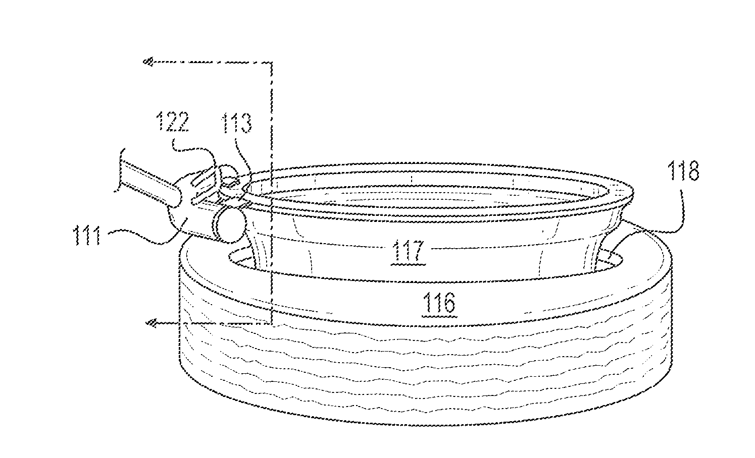
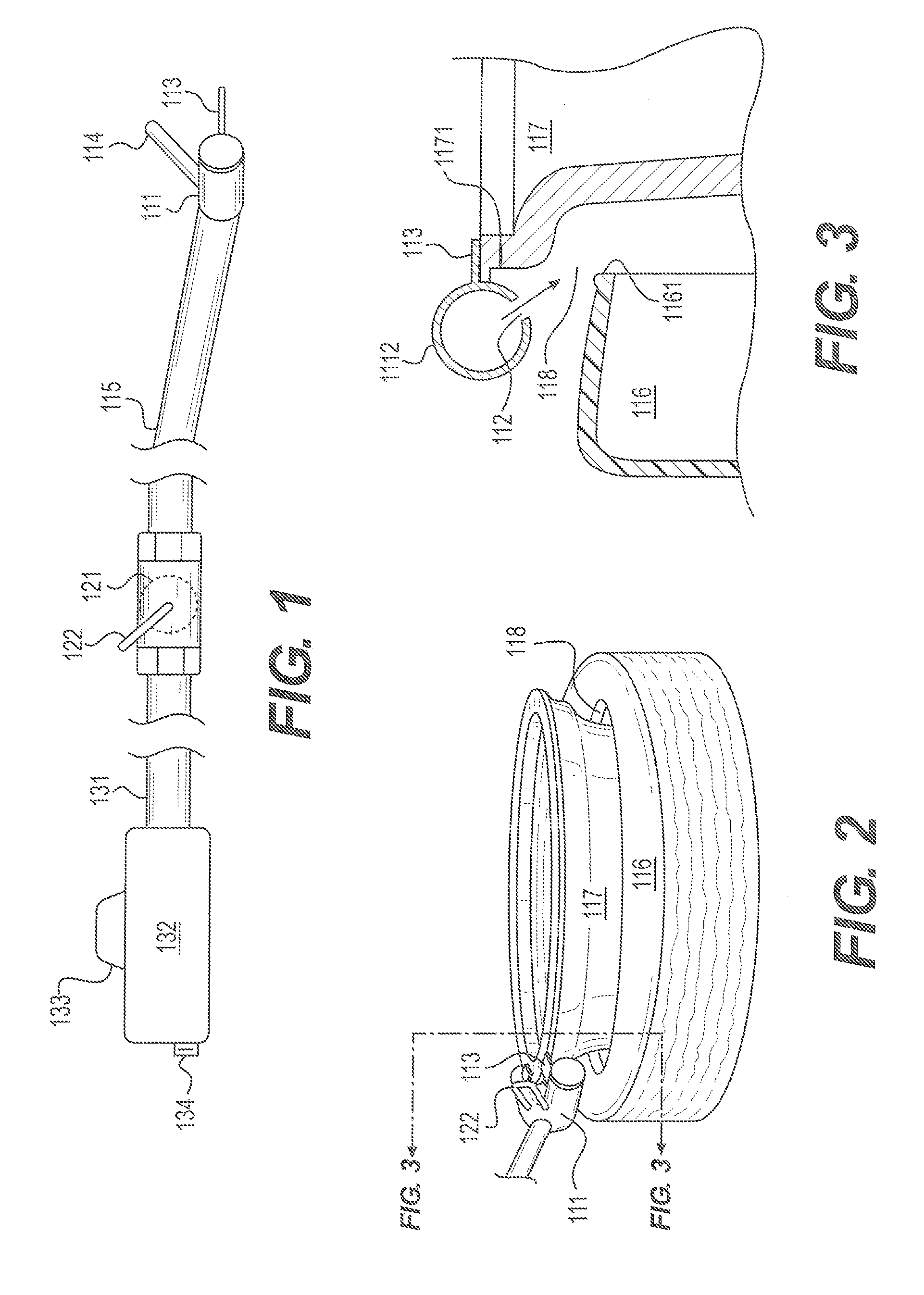
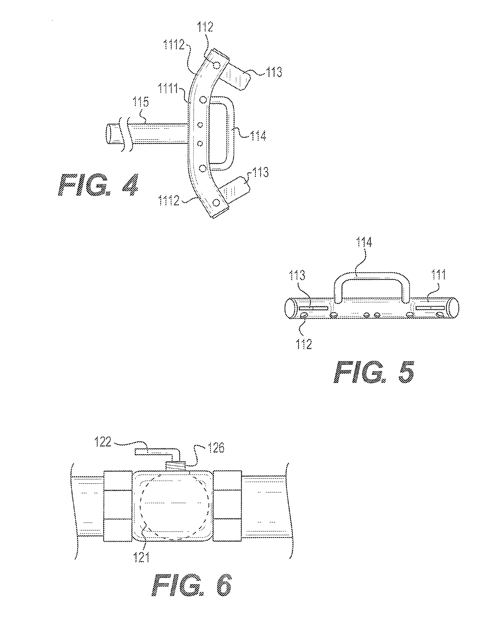
[0006]In accordance with one embodiment of the present invention, a seating apparatus for seating a tire on a rim is provided. The seating apparatus includes a rigid body with a plurality of holes to vent air into a gap between the tire and the rim, a pipe coupled to said b

Problems solved by technology

A challenge associated with changing a tubeless tire is the difficulty associated with establishing the initial seal between the bead of the tire and the bead-seating surface of the rim on which the tire is to be mounted.
This difficulty results from the fact that, when a tire is uninflated, the open space or gap between its bead and the bead-seating surface of the rim is often so large that seating is prevented by the leakage of air therethrough.
This problem is more apparent in the case of heavy truck tires, particularly radial truck tires, because the stiffness of such tires makes them resistant to forces that tend to reduce the gap sufficiently for seating to occur.

Method used


Image

  • Apparatus and method for sealing tubeless tires
  • Apparatus and method for sealing tubeless tires
  • Apparatus and method for sealing tubeless tires

Examples


Embodiment Construction

[0022]The present invention addresses at least the issues discussed above by providing a bead seating apparatus and method which employ a pneumatic pulse having a leading edge with a short rise time both to impart momentum to the bead and inject air into the tire. This pulse of air thereby initiates a bead motion in the tire which results in the progressive seating thereof. Ease of use and portability are addressed through the inclusion of means to counteract the recoil effect resulting from venting the pulse of air and providing a modular design. The various components of the apparatus described below can be easily disengaged from each other and re-coupled for use.

[0023]Referring now to the drawings, like reference numerals designate identical or corresponding parts throughout the drawings.

[0024]FIG. 1 depicts a seating apparatus 100 according to an exemplary embodiment. The seating apparatus 100 includes a rigid body 110 including a protrusions 113, a handle 114, and a pipe 115 th...


PUM


Abstract

An apparatus and method to seat a tire on a rim are described. Protrusions and a handle on the apparatus allow a user to brace the protrusions against the rim to prevent blow back when air is vented into the gap between the tire and the rim to seat the tire bead. The air is vented through a plurality of holes in the apparatus and the flow of the air into the apparatus is controlled by positioning a bridge handle of a flow control valve situated between the apparatus and a tank of air.

Description

CROSS-REFERENCE TO RELATED APPLICATIONS[0001]This application claims priority to the provisional U.S. patent application entitled Pneumatic Method and Apparatus for Sealing Tubeless Tires, filed Apr. 7, 2010, having a Ser. No. 61 / 321,760, and the provisional U.S. patent application entitled Self Closing Bridge Handle, filed Sep. 23, 2010, having a Ser. No. 61 / 403,879, the disclosures of both of which are incorporated herein by reference in their entirety.FIELD OF THE INVENTION[0002]The present invention relates generally to establishing a seal between the bead of a tire and a rim. More particularly, the present invention relates to a seating apparatus and method to seat a tire on a rim by employing a pneumatic pulse.BACKGROUND OF THE INVENTION[0003]A challenge associated with changing a tubeless tire is the difficulty associated with establishing the initial seal between the bead of the tire and the bead-seating surface of the rim on which the tire is to be mounted. This difficulty ...

Claims


Application Information

Patent Timeline
IPC IPC(8): B60C25/132
CPCB60C25/145
Inventor WHITE, MICHAEL R.
Owner BOSCH AUTOMOTIVE SERVICE SOLUTIONS
Learn More