
Fluid cooling during hot-blow-forming of metal sheets and tubes

Inactive Publication Date: 2011-10-06
GM GLOBAL TECH OPERATIONS LLC
View PDF4 Cites 12 Cited by
  • Summary
  • Abstract
  • Description
  • Claims
  • Application Information

AI Technical Summary

Benefits of technology

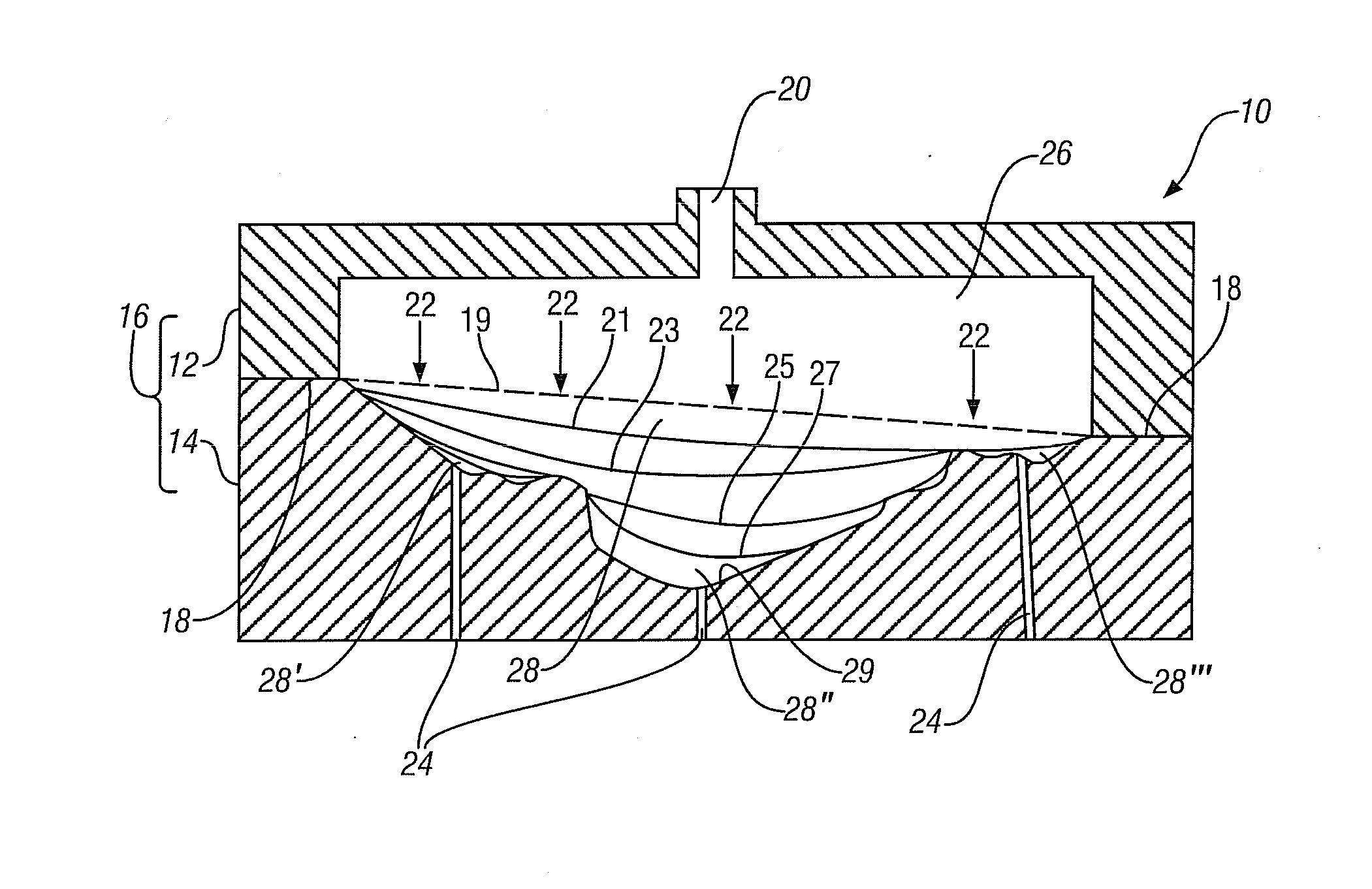
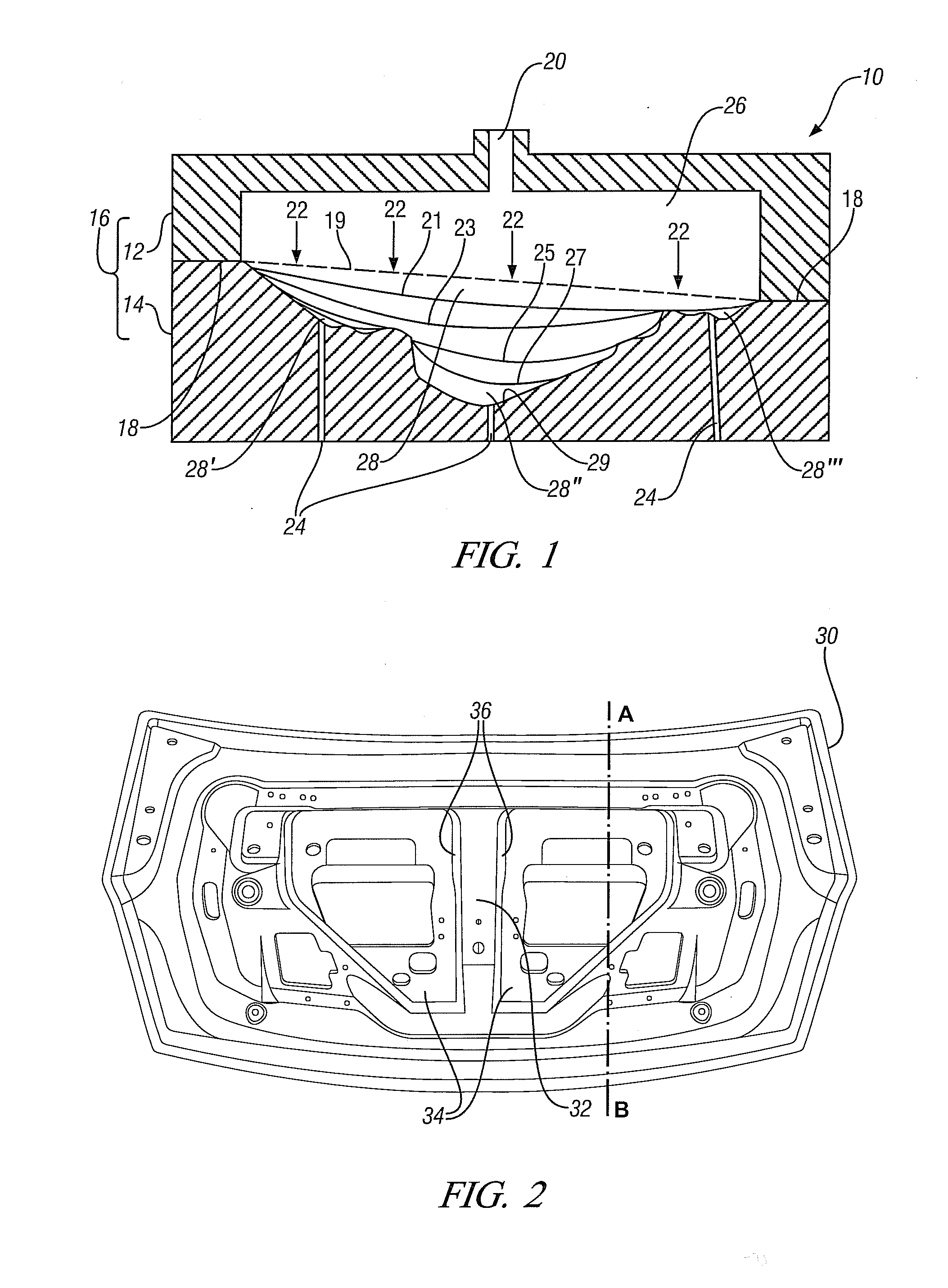
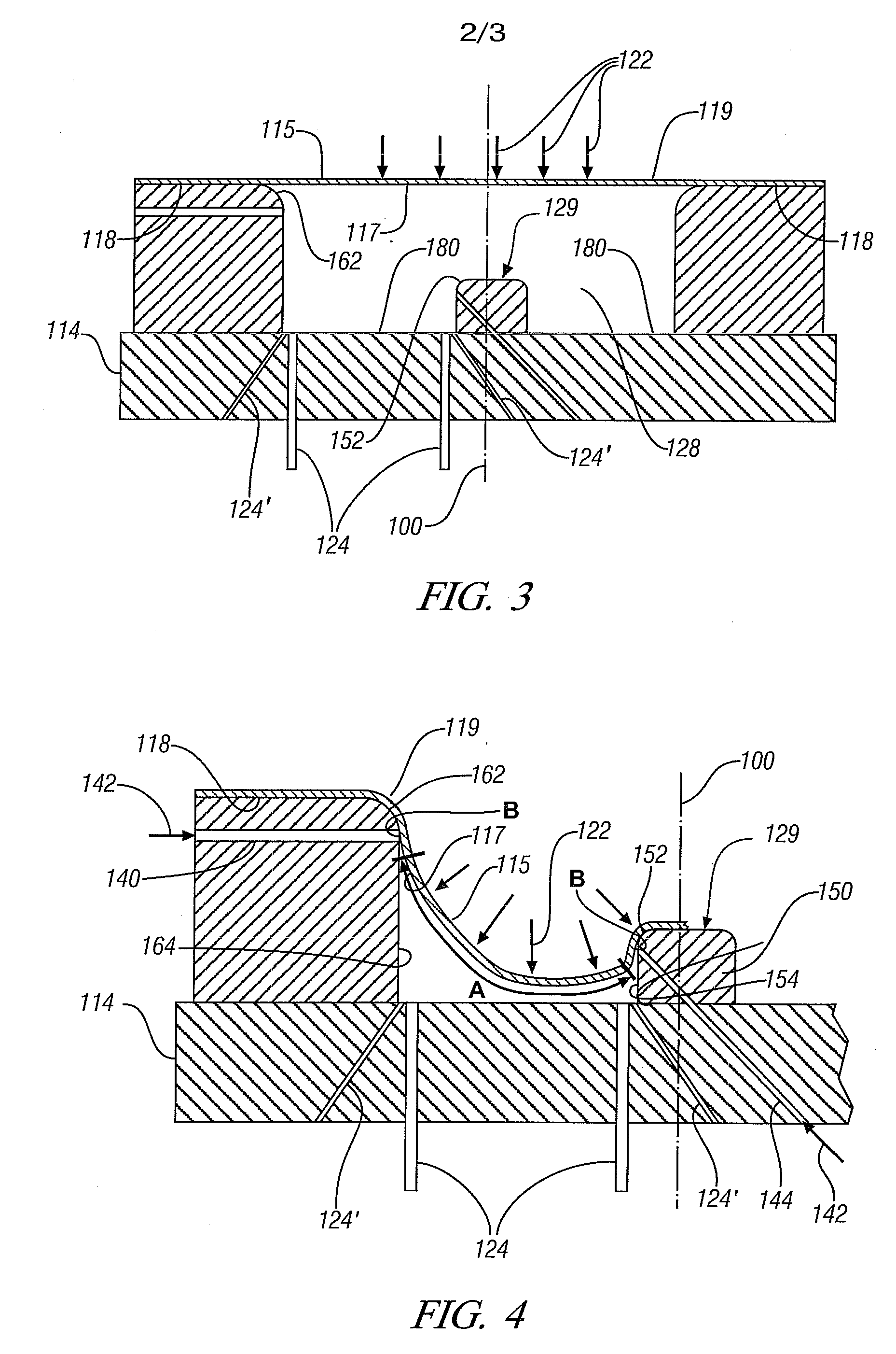
[0010]In accordance with embodiments of the invention, identified regions of a thin metal workpiece, which has been heated more or less uniformly to its forming temperature, are selectively cooled during a hot-blow-forming process. The cooling is suitably accomplished by directing a stream of ambient air (or other suitable fluid) against one or both of the sides of the metal in the identified surface regions of the workpiece. The cooling fluid stream is used and controlled to reduce the strain and thinning of the forming metal in the identified, critical forming regions. This reduction in straining or thinning is a consequence of the metal in the cooled region becoming harder. The selected cooling strategy is to shift the strain into larger adjacent areas of the thinning metal workpiece as it undergoes the forming operation, and enhance the overall formability through more uniform thinning of the workpiece. This shifting of the strain permits the workpiece to achieve the intended shape of the forming step that it is experiencing.
[0012]Thus, in accordance with practices of the invention, the hot-blow-forming process uses two fluid streams. One fluid, which may be air, is used to pressurize and form the heated metal workpiece against a shaping surface. The second fluid, which may also be air, is used to locally cool selected regions of the workpiece as it is shaped. The cooling stream or streams are used to permit the hot-blow-forming of more complex shapes in a metal workpiece and to accomplish such forming in relatively short forming periods of a minute or so.

Problems solved by technology

But it is observed that the dome height of the expanding metal is often limited by excessive thinning and splitting of the strained metal near the pole region of the forming dome shape.
This may mean that a desired article shape cannot be made from available metal alloys using hot-blow-forming.
But this limits production rates and the utilization of expensive forming equipment.

Method used


Image

  • Fluid cooling during hot-blow-forming of metal sheets and tubes
  • Fluid cooling during hot-blow-forming of metal sheets and tubes
  • Fluid cooling during hot-blow-forming of metal sheets and tubes

Examples


Embodiment Construction

[0019]This invention is especially useful in hot-blow-forming of light metal alloys such as aluminum-based alloys and magnesium based alloys which to not tend to be as formable as low carbon steel alloys. Some exemplary materials suitable for practice of hot-blow-forming include aluminum alloy AA5083 (composition in percentage by weight: Mg, 4.0-4.9; Mn, 0.4-1.0; Zn≦0.25; balance aluminum) and magnesium alloy AZ31B (composition in percentage by weight: Al, 2.5-3.5; Zn, 0.6-1.4; Mn, ≧0.2, balance magnesium). The AZ31 magnesium alloy may be hot-blow-formed in both the annealed (AZ31B—O) and half hard (AZ31B-H24) conditions.

[0020]Hot-blow-forming is a forming process in which a heated workpiece, typically in the form of a cold-rolled sheet or a tube, is progressively deformed by maintaining a pressure differential through the workpiece thickness for some period of time, typically ranging from 30 to 300 seconds. The deformation will be accompanied by the accumulation of strain, both in ...


PUM

PropertyMeasurementUnit
Thicknessaaaaaaaaaa
Thicknessaaaaaaaaaa
Temperatureaaaaaaaaaa

Abstract

Metal sheets and thin-wall metal tubes may be heated to a hot working temperature and transformed by a hot-blow-forming step to achieve shapes, difficult to attain, without excessive thinning or strain causing damage to the workpiece based on the inherent formability of the metal alloy. The stages of forming of the intended shape in the metal workpiece are analyzed and workpiece regions of potential damage during forming are identified. Then, during actual forming, these regions of the hot workpiece are selectively cooled with air (or other cooling fluid) to reduce thinning or strain in the critical region(s) and to redistribute this strain to adjacent lower strain areas of the workpiece. This hot-blow-forming practice is particularly useful in attaining complex shapes in workpieces of aluminum-based alloys and magnesium-based alloys.

Description

TECHNICAL FIELD[0001]This disclosure pertains to the use of a pressurized fluid acting against one side of a heated, thin metal workpiece to push and stretch the heat-softened workpiece. Often the workpiece is stretched into conformance with the forming surface of a tool positioned at the other side of the workpiece to form the metal into a complex shape. More specifically, this disclosure pertains to the use of a second fluid to selectively cool predetermined high-strain locations of the deforming metal to enhance the overall formability of the workpiece and to minimize localized damage as it is being formed.BACKGROUND OF THE INVENTION[0002]There is interest in forming thin, relatively light-weight, aluminum-based alloy workpieces and magnesium-based alloy workpieces into automotive body panels or generally tubular body or frame structures, or the like. Such panels may be formed from initially flat, sheet metal blanks having dimensions of, e.g., about 1000 mm×1500 mm×1-3 mm. Tubula...

Claims


Application Information

Patent Timeline
IPC IPC(8): B21D26/02B23Q11/10
CPCB21D26/021
Inventor CARTER, JON T.VERMA, RAVIKRAJEWSKI, PAUL E.
Owner GM GLOBAL TECH OPERATIONS LLC
Learn More