Optically-functional film and method of manufacturing the same, display and method of manufacturing the same

Active Publication Date: 2011-09-29
JOLED INC
View PDF1 Cites 30 Cited by
  • Summary
  • Abstract
  • Description
  • Claims
  • Application Information

AI Technical Summary

Benefits of technology

[0005]It is desirable to provide an optically-functional film allowed to prevent peeling due to adhesion failure or degradation due to moisture diffusion, and a method of manufacturing the same, and a display including the optically-functional film and allowed to prevent a decline in luminance and a color change depending on a viewing angle and a method of manufacturing the same.
[0012]In the display according to the embodiment, the optically-functional film according to the above-described embodiment is arranged on a light extraction side of the display panel; therefore, the asperities allow incident light which enters into a top surface of the outermost layer to be scattered. Therefore, high directivity of EL light emission generated in the organic light-emitting element is released to prevent a decline in luminance depending on a viewing angle. Accordingly, a color change is prevented.
[0015]In the optically-functional film according to the embodiment, as asperities are arranged on the top surface of the outermost layer, the asperities are allowed to have an optical function such as scattering, and unlike related art, it is not necessary to separately bond a binder to which a scatterer is added, and moisture diffusion from the binder is prevented, and peeling due to adhesion failure or deterioration due to moisture diffusion is preventable. When the display is configured with use of the optically-functional film, a decline in luminance depending on a viewing angle and a color change caused thereby are prevented; therefore, higher-quality display is achievable.
[0016]In the method of manufacturing an optically-functional film, and the first and second methods of manufacturing a display according to the embodiment, the generation of plasma is stopped, and then restarts during or after the formation of the intermediate layer to form the silicon-containing particles in the intermediate layer or on a top surface of the intermediate layer, and the outermost layer is formed with use of the silicon-containing particle as nuclei to form asperities on the top surface thereof; therefore, the optically-functional film or the display according to the embodiment is allowed to be manufactured easily.

Problems solved by technology

However, in such a configuration in related art, there are possibilities of peeling due to adhesion failure in an interface with a protective film, deterioration of the protective film due to moisture diffusion from a binder absorbing water, and the like.

Method used


Image

  • Optically-functional film and method of manufacturing the same, display and method of manufacturing the same
  • Optically-functional film and method of manufacturing the same, display and method of manufacturing the same
  • Optically-functional film and method of manufacturing the same, display and method of manufacturing the same

Examples


first embodiment

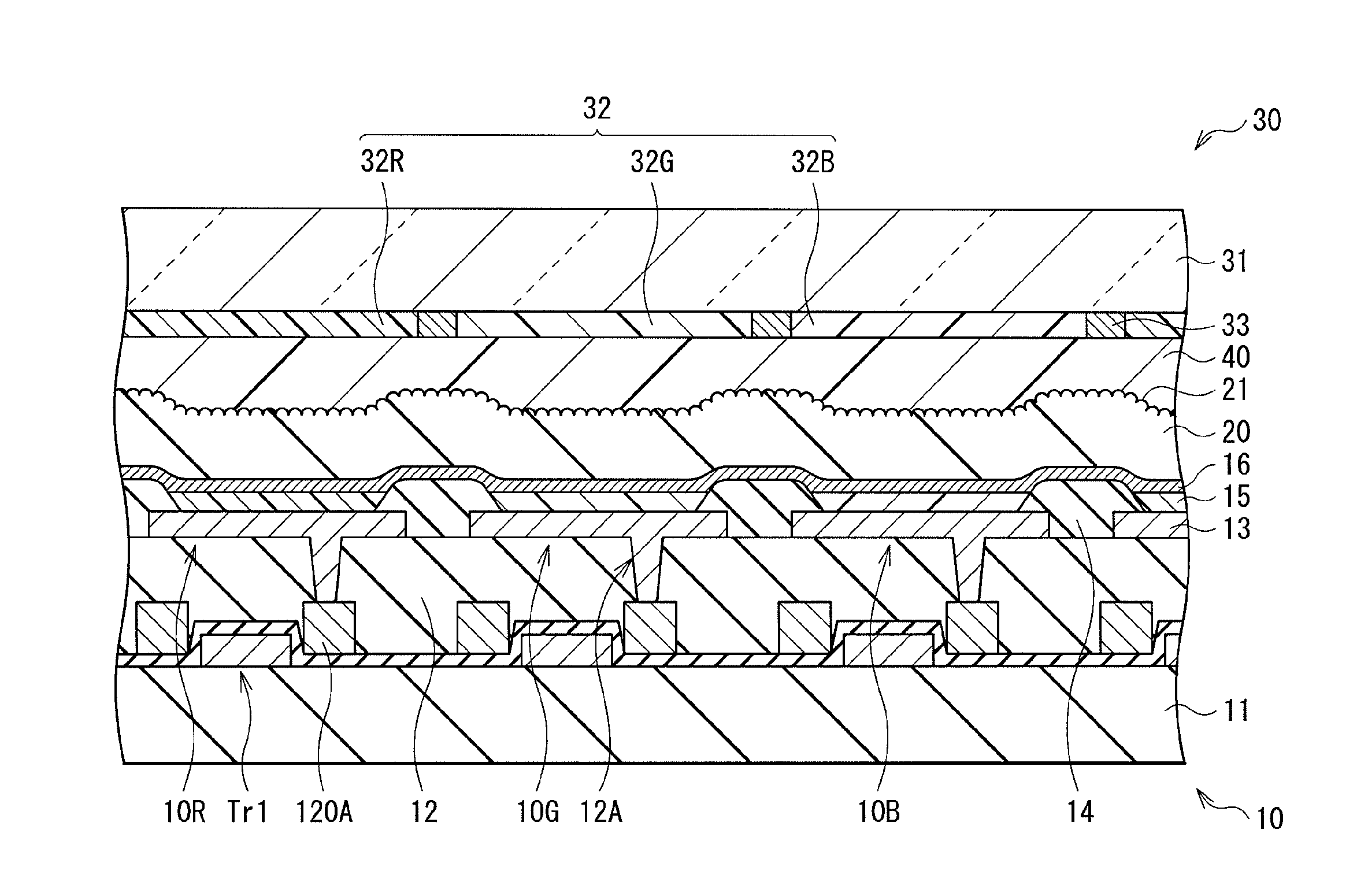
[0054]FIG. 1 illustrates a configuration of a display according to a first embodiment. The display is used as an organic EL television or the like, and in the display, for example, a plurality of organic light-emitting elements 10R, 10G and 10B which will be described later are arranged in a matrix form as a display region 110 on a substrate 11. A signal line drive circuit 120 and a scanning line drive circuit 130 as drivers for picture display are arranged around the display region 110.

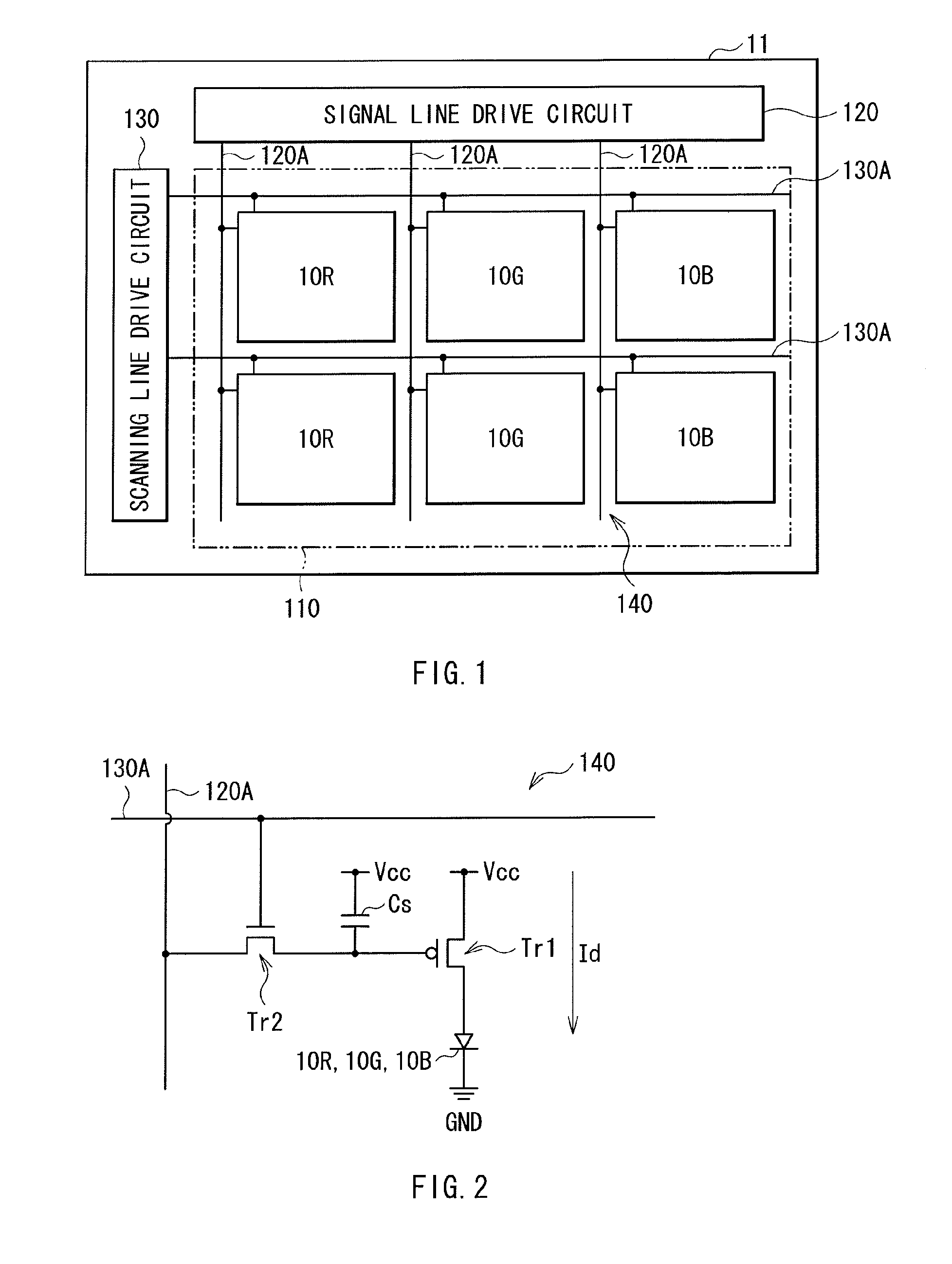
[0055]A pixel drive circuit 140 is arranged in the display region 110. FIG. 2 illustrates an example of the pixel drive circuit 140. The pixel drive circuit 140 is an active drive circuit formed below a first electrode 13 which will be described later. In other words, the pixel drive circuit 140 includes a driving transistor Tr1 and a writing transistor Tr2, a capacitor (retention capacitor) Cs between the driving transistor Tr1 and the writing transistor Tr2, and the organic light-emitting element 1...

second embodiment

[0122]FIG. 20 illustrates a sectional configuration of the display region 110 in a display according to a second embodiment. The display has the same configuration as that of the first embodiment, except that the optically-functional film 20 is arranged on the adhesive layer 40 side of the sealing panel 30. Therefore, in the following description, like components are denoted by like numerals as of the first embodiment.

[0123]As in the case of the first embodiment, the display panel 10 includes the organic light-emitting elements 10R, 10G and 10B on the substrate 11. If necessary, the organic light-emitting elements 10R, 10G and 10B are covered with a protective film 17 made of silicon nitride or silicon oxide.

[0124]The optically-functional film 20 has the same configuration as that of the first embodiment, except that the optically-functional film 20 is arranged on the color filter 32 and the light-shielding film 33 of the sealing panel 30. In other words, as illustrated in FIG. 21, ...

application example 2

of Display

[0144]FIG. 27 illustrates an appearance of a digital camera to which the display according to any of the above-described embodiments is applied. The digital camera has, for example, a light-emitting section for a flash 410, a display section 420, a menu switch 430, and a shutter button 440, and the display section 420 is configured of the display according to any of the above-described embodiments.


PUM

PropertyMeasurementUnit
Temperatureaaaaaaaaaa
Densityaaaaaaaaaa

Abstract

There are provided an optically-functional film allowed to prevent peeling due to adhesion failure or deterioration due to moisture diffusion and a method of manufacturing the same, and a display allowed to prevent a decline in luminance and a color change depending on a viewing angle and a method of manufacturing the same. The optically-functional film includes: an intermediate layer, made of an insulating material including silicon, and having silicon-containing particles therein or on a top surface thereof; and an outermost layer made of the same material as that of the intermediate layer, whereas having a density higher than that of the intermediate layer, and having a bottom surface in contact with a top surface of the intermediate layer and a top surface with asperities.

Description

CROSS REFERENCES TO RELATED APPLICATIONS[0001]The present application claims priority to Japanese Priority Patent Application JP 2010-068123 filed in the Japan Patent Office on Mar. 24, 2010, the entire content of which is hereby incorporated by reference.BACKGROUND[0002]The present application relates to an optically-functional film suitable as a scattering film or the like for improving image quality of a display and a method of manufacturing the same. Moreover, the application relates to a display including the optically-functional film and a method of manufacturing the same.[0003]An example of a display using a self-luminous element is a display using an organic light-emitting element (an organic EL (electroluminescence) element). However, in the display in related art, high directivity of EL light emission causes a decline in luminance depending on a viewing angle, thereby causing a color change such as color unevenness. Therefore, for example, as described in Published Japanes...

Claims


Application Information

Patent Timeline
IPC IPC(8): H01J1/62B32B7/02H05H1/24B32B37/14
CPCG02B5/0215H01L51/5218H01L51/5253Y10T428/24992H01L51/5281H01L2251/5315H01L2251/5369H01L51/5268H10K50/818H10K50/844H10K50/854H10K50/86H10K2102/3026H10K2102/331
Inventor ABE, KAORU
Owner JOLED INC
Why Eureka
Try Eureka