Eureka AIR delivers breakthrough ideas for toughest innovation challenges, trusted by R&D personnel around the world.

Hybrid emergency ejection system

a technology of emergency escape and hybrid ejection system, which is applied in the direction of emergency equipment, aircraft ejection means, transportation and packaging, etc., can solve the problem that the pilot is given a short time to override any automatic deployment of the system

Inactive Publication Date: 2011-09-29
MONTEFORTE MICHAEL A
View PDF7 Cites 17 Cited by
  • Summary
  • Abstract
  • Description
  • Claims
  • Application Information

AI Technical Summary

Benefits of technology

[0015]It is an object of the present invention to overcome the deficiencies in the prior art by proposing an aircraft with a series of detachable passenger escape cabins which extend longitudinally along the fuselage of the aircraft, including the cockpit, but excludes the tail portion and whose detachment takes place in the vertical upward direction, thereby effecting an immediate moving away from the vicinity of the remainder of the aircraft wherein there always exists the risk of crash, fire or explosion.
[0016]It is a further object of the present invention to provide an emergency escape system from a commercial aircraft that includes individual escape pods. It should be noted that the invention can be applied to private jets as well. Each pod has its own ejection means, such as conventional rocket motors or explosive devices to propel the pods from the aircraft fuselage. Each pod also has individual parachute means to slow the descent of the pods after ejection, and individual air bags to minimize the shock when the pod collides with the earth. The air bags also provide for flotation should the pod land in water.
[0017]The ejection system is normally controlled by the pilot. However, flight sensors could be utilized to operate the system automatically in an emergency, such as when the plane loses power for a certain period of time or an extreme drop in elevation occurs. Of course, the pilot is given a short time to override any automatic deployment of the system.
[0018]Each pod according to the invention would hold several passengers. In an emergency the pods are ejected and the passenger is provided with oxygen masks as in normal aircraft, to prevent hypoxia.

Problems solved by technology

Of course, the pilot is given a short time to override any automatic deployment of the system.

Method used


Image

  • Hybrid emergency ejection system
  • Hybrid emergency ejection system
  • Hybrid emergency ejection system

Examples


Embodiment Construction

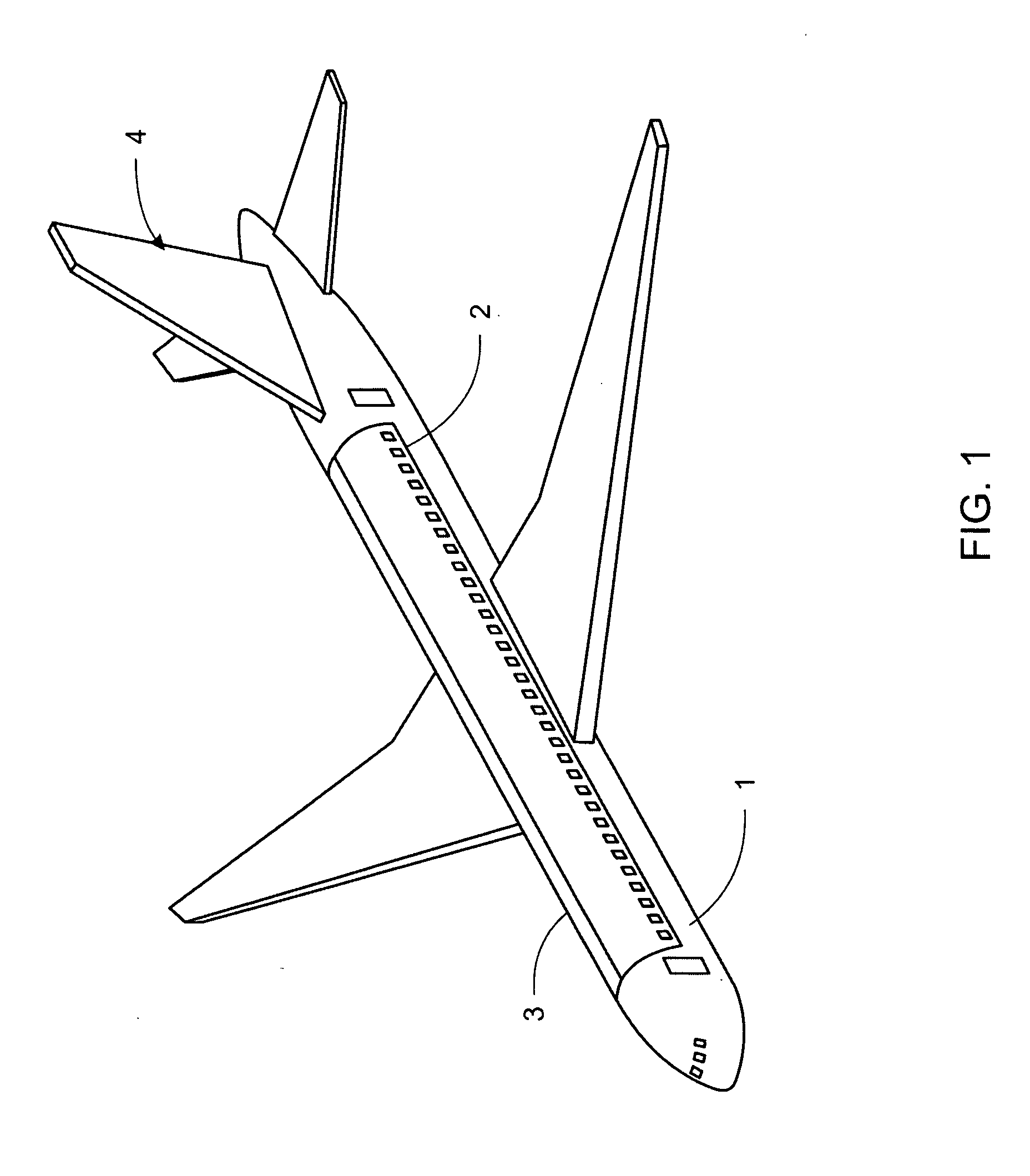
[0025]Referring to FIG. 1, a conventional passenger aircraft (1) is provided with a left cabin cover (2) and a right cabin cover (3). In an emergency situation where a normal landing is either impossible or highly dangerous, the cabin covers (2) and (3) are separated from the aircraft and ejected to the left and right of the aircraft (1). This separation is normally accomplished by the installation of detonator cord along the separation points, such as cords of lead azide. The pilot or co-pilot controls ignition of the detonator cord through electrically controlled squids that ignite the cord. Lead azide burns rapidly and at an extremely high temperature, and burns a separation line where it is embedded in or along the aircraft body. Explosive charges are mounted along the sides of the cabin covers (2) and (3) which propel the cabin covers (2) and (3) to the left and right of the fuselage, respectively, to prevent the cabin covers (2) and (3) from striking the pods or tail wings of ...


PUM


Abstract

An emergency escape sequence for a commercial aircraft is shown. Individual pods that are separable from the aircraft are ejected individually, following the separation and ejection of the upper cabin from the fuselage. Parachutes are deployed to assist in the safe descent of the pods. Airbags are also deployed to soften the landing and provide flotation in case of a water landing.

Description

CROSS-REFERENCE TO RELATED APPLICATIONS[0001]This application is based on U.S Provisional Patent Application Ser. No. 61 / 341,025 filed Mar. 26, 2010, and claims benefit thereof.STATEMENT REGARDING FEDERALLY SPONSORED RESEARCH OR DEVELOPMENT[0002]Not applicable.THE NAMES OF THE PARTIES TO A JOINT RESEARCH AGREEMENT[0003]Not applicable.REFERENCE TO A SEQUENCE LISTING OR A COMPUTER PROGRAM LISTING[0004]Not applicable.BACKGROUND OF THE INVENTIONFIELD OF THE INVENTION[0005]The invention relates to the field of aircraft emergency escape equipment, specifically adapted to commercial passenger aircraft with large numbers of passengers. More specifically it relates to an aircraft comprising a detachable passenger escape pods, which are mounted onto the fuselage of the aircraft via a speedily released set of connectors. The pods are equipped with parachutes and airbags and with autonomous mechanisms ensuring their vertical upward detachment from the remainder of the airplane which is thence l...

Claims


Application Information

Patent Timeline
Patent Type & Authority Applications(United States)
IPC IPC(8): B64D25/12
CPCB64D25/12
Inventor MONTEFORTE, MICHAEL A.
Owner MONTEFORTE MICHAEL A
Why Eureka
Eureka Blog
Learn More