
Power storage device and manufacturing method thereof

a technology of power storage and manufacturing method, which is applied in the direction of positive electrodes, electrode manufacturing processes, cell components, etc., can solve the problems of large capacitance, high bulk resistivity, and poor electronic conduction, so as to achieve rapid charge and discharge, large capacitance, and the effect of accelerating the diffusion of lithium ions

Inactive Publication Date: 2011-09-22
SEMICON ENERGY LAB CO LTD
View PDF14 Cites 14 Cited by
  • Summary
  • Abstract
  • Description
  • Claims
  • Application Information

AI Technical Summary

Benefits of technology

[0007]Because lithium iron phosphate has high bulk resistivity, charge and discharge of a power storage device in which lithium iron phosphate is used as a positive electrode active material may be slow.
[0013]The particle size of lithium iron phosphate is nano-sized. Accordingly, the diffusion length of lithium ions can be shortened in lithium iron phosphate. Thus, the capacitance of a power storage device can be increased.
[0014]When a positive electrode is manufactured using a lithium iron phosphate particle with such a small particle size, lithium iron phosphate particles are aggregated. However, by using a carbon material as a support on a surface of lithium iron phosphate particles with a small particle size, aggregation of lithium iron phosphate particles can be suppressed. By suppressing the aggregation of lithium iron phosphate particles, the resistance of the whole positive electrode can be decreased. Therefore, rapid charge and discharge of the power storage device can be achieved. In this specification, “lithium iron phosphate particles whose surface is supported by a carbon material” also means that lithium iron phosphate particles are carbon-coated. Further, in this specification, “lithium iron phosphate particles whose surface is supported by a carbon material” means that the surface of lithium iron phosphate particles is covered with a carbon material even though the surface of the lithium iron phosphate particles is not entirely covered with the carbon material.
[0023]According to one embodiment of the disclosed invention, a power storage device with rapid charge and discharge can be obtained. Further, diffusion of lithium ions can be accelerated. Thus, a power storage device having a large capacitance can be obtained.

Problems solved by technology

However, lithium iron phosphate (LiFePO4) having such a large capacitance has the disadvantages of high bulk resistivity (electric conductivity of lithium iron phosphate is about 6.8×10⁻⁹ S / cm).
“High bulk resistivity” means that electronic conduction is bad.
Because lithium iron phosphate has high bulk resistivity, charge and discharge of a power storage device in which lithium iron phosphate is used as a positive electrode active material may be slow.
In addition, lithium iron phosphate is disadvantageous in that diffusion of lithium (Li) ions is slow.
However, because diffusion of lithium ions in a crystal of lithium iron phosphate is slow, it is difficult for lithium ions to reach the inside of the crystal of lithium iron phosphate.

Method used


Image

  • Power storage device and manufacturing method thereof
  • Power storage device and manufacturing method thereof
  • Power storage device and manufacturing method thereof

Examples


embodiment 1

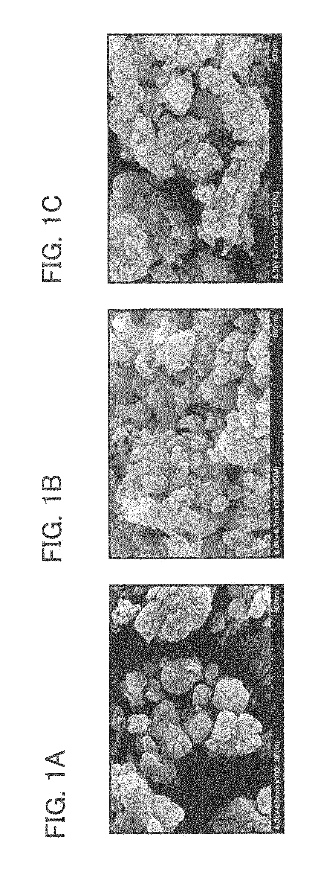
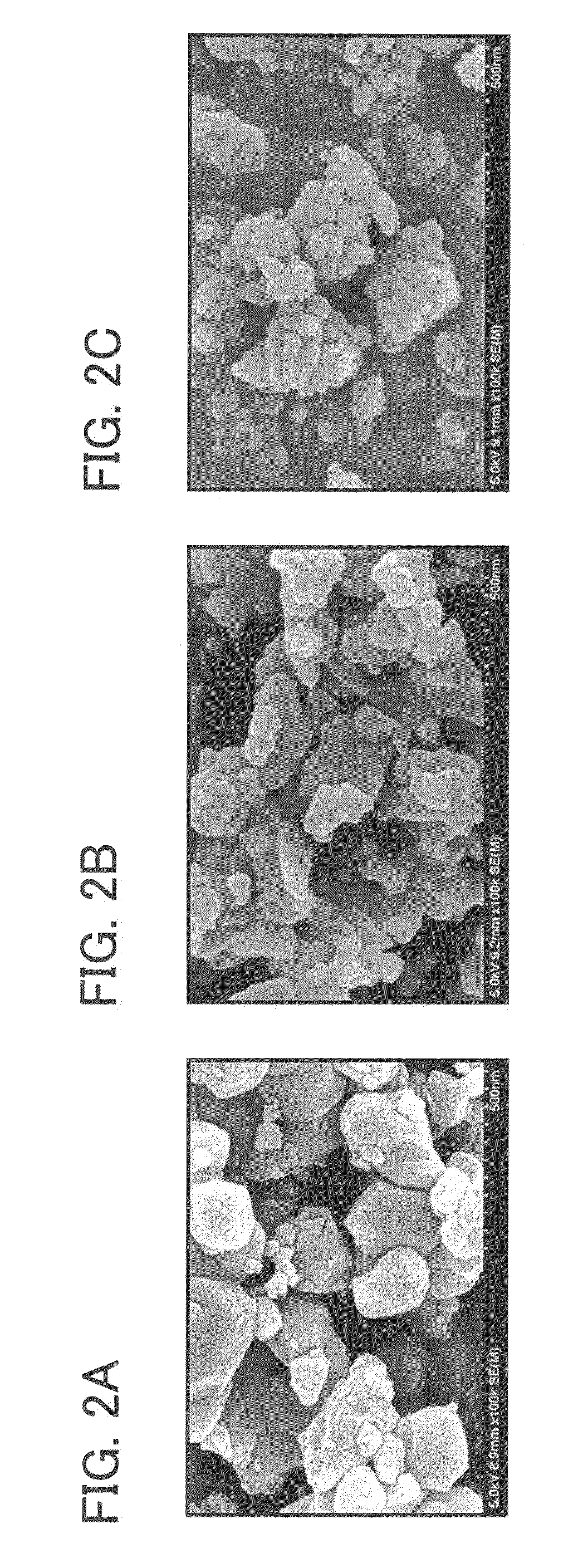
[0053]A power storage device of this embodiment and a method for manufacturing the power storage device are described with reference to FIGS. 1A to 1C, FIGS. 2A to 2C, FIGS. 3A to 3C, FIGS. 4A to 4C, FIG. 5, FIG. 6, FIG. 7, FIG. 8, FIG. 9, FIG. 10, FIGS. 11A to 11C, FIG. 12, FIG. 13, FIG. 14, FIG. 15, FIG. 16, FIG. 17, FIG. 18, FIG. 19, FIG. 20, FIG. 21, FIG. 22, FIG. 23, FIG. 24, FIG. 25, FIGS. 26A and 26B, FIG. 27, and FIG. 28.

[0054]In this embodiment, lithium iron phosphate (LiFePO4) is used as a positive electrode active material of a secondary battery. Lithium iron phosphate, a manufacturing method thereof, and characteristics thereof are described below. Then, a secondary battery in which lithium iron phosphate is used as a positive electrode active material, a manufacturing method thereof, and characteristics thereof are described.

[0055]First, a manufacturing method of lithium iron phosphate (LiFePO4) particles is described below.

[0056]As a material of lithium iron phosphate,...


PUM


Abstract

A power storage device comprising a positive electrode which includes in a positive electrode active material layer, lithium iron phosphate particles whose surface is supported by a carbon material and whose half width of the X-ray diffraction peak is less than or equal to 0.17°, or greater than or equal to 0.13° and less than or equal to 0.165′ or whose particle size is greater than or equal to 20 nm and less than 50 nm or greater than or equal to 30 nm and less than 40 nm; or a method for manufacturing a power storage device comprising the steps of mixing the lithium iron phosphate particles, a conduction auxiliary agent, and a binder so as to be a paste, and applying the paste on a current collector, thereby manufacturing a positive electrode.

Description

TECHNICAL FIELD[0001]One embodiment of the disclosed invention relates to a power storage device and a manufacturing method thereof.BACKGROUND ART[0002]In recent years, with an increase of environmental engineering, development of power generating technologies which pose less burden on the environment (e.g., solar power generation) than conventional power generation methods has been actively conducted. Concurrently with the development of power generation technology, development of power storage technology has also been underway.[0003]A power storage technology includes, for instance, a lithium ion secondary battery. Lithium ion secondary batteries are widely prevalent since their energy density is high and because they are well suited for miniaturization. As a material used for a positive electrode of the lithium ion secondary battery, there is lithium iron phosphate (LiFePO4) having an olivine structure, for example (see Patent Document 1).[0004]Lithium iron phosphate (LiFePO4) ha...

Claims


Application Information

Patent Timeline
IPC IPC(8): H01M4/136H01M4/139
CPCH01M4/0471H01M4/136H01M4/1397H01M4/366Y02E60/122H01M4/625H01M10/052H01M2004/021H01M2004/028H01M4/5825Y02E60/10
Inventor KAWAKAMI, TAKAHIROYAMAKAJI, MASAKITAKAHASHI, NADINE
Owner SEMICON ENERGY LAB CO LTD
Learn More