
Process and apparatus for continuous flow synthesis of nanocrystals

Inactive Publication Date: 2011-09-22
LIFE TECH CORP
View PDF16 Cites 30 Cited by
  • Summary
  • Abstract
  • Description
  • Claims
  • Application Information

AI Technical Summary

Benefits of technology

[0011]In another embodiment, a reaction mixture could be processed through two reactors in series, thereby increasing residence time of a reaction mixture in the heated reactor zone. In a further embodiment, a first reactor could be used to produce and grow core nanocrystals, and a shell could be added in a second reactor. It will be clear to one of skill in the art that other configurations are possible, for example, to install an additional shell on a core / shell nanocrystal.
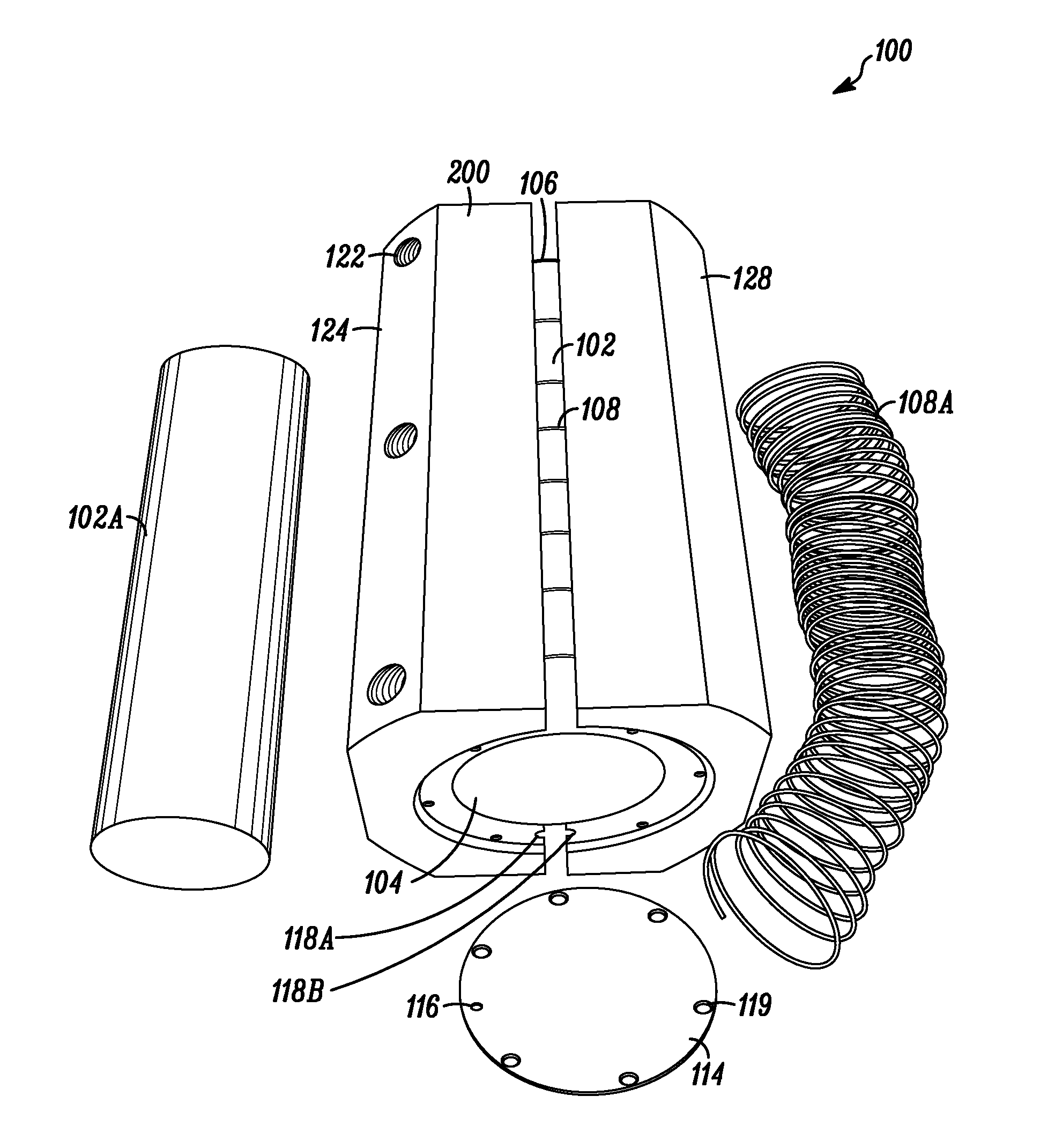
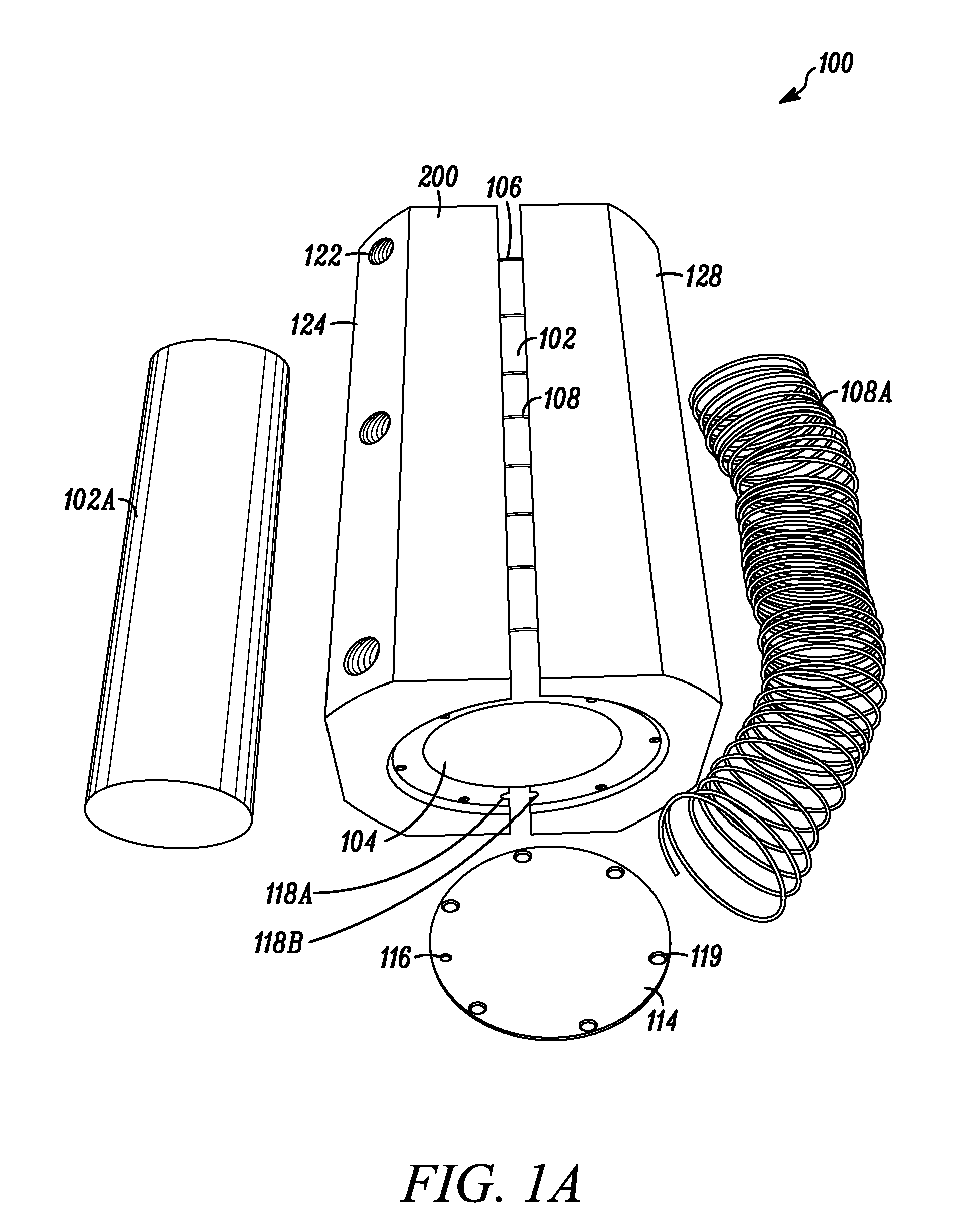
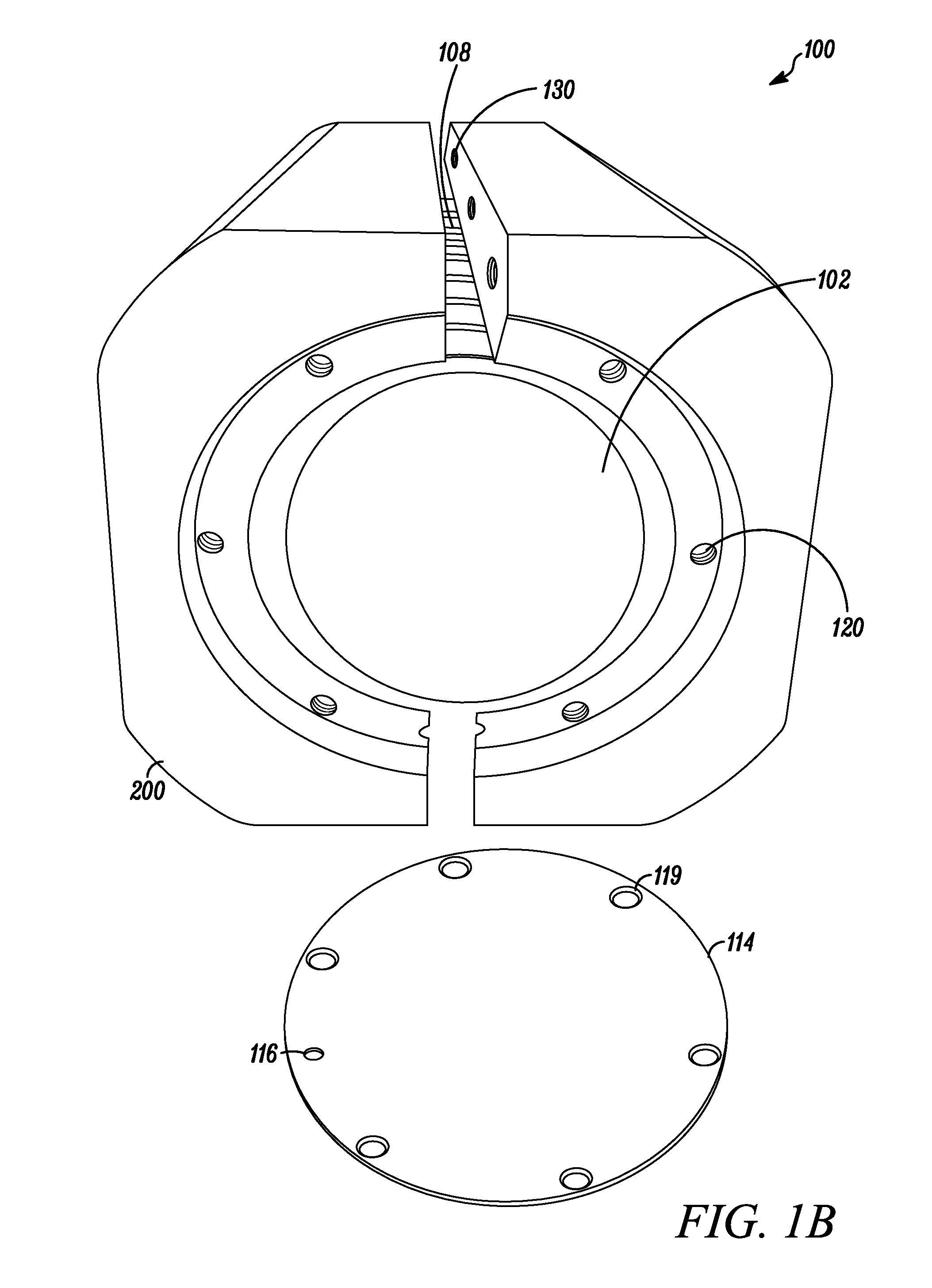
[0026]The reactor provided herein provides a very flexible design that can be modified in many parameters as described herein while being capable of providing a stable temperature environment for a chemical reaction that occurs inside the reactor tube. The primary purpose of the design is for use with a heated reaction, for which the design provides multiple factors that contribute to a stable operating temperature for the reactor tube and its contents. In some embodiments, the core and / or sleeve are thermostatically maintained at a desired temperature, typically both at the same temperature, thereby maintaining a uniform temperature along the length of the reactor tube where it resides inside the reactor. In one embodiment, the helical winding comprises stainless steel tubing. In another embodiment, the reactor comprises a means for changing the residence time of a reaction mixture in the helical reaction channel. In other embodiments, the reactor comprises a means for heating the reaction mixture in the reactor, and optionally at least one temperature sensing device to monitor the temperature of at least one portion of the core, the sleeve, or both. In some embodiments, the helical winding provides a means for turbulent flow of the reaction mixture in the reaction channel. In many embodiments, the core, sleeve and helical structure are modular, separate units, and can be repeatedly assembled to form the reactor and disassembled for convenient changing of the length of the helical winding.

Problems solved by technology

On the other hand, increasing the pitch of the winding results in a decrease of overall reaction channel length within the reactor and a corresponding decrease in the residence time.

Method used


Image

  • Process and apparatus for continuous flow synthesis of nanocrystals
  • Process and apparatus for continuous flow synthesis of nanocrystals
  • Process and apparatus for continuous flow synthesis of nanocrystals

Examples


example 1

Process Flow Diagram

[0176]FIG. 3 is a process flow diagram illustrating one example of a rudimentary system embodying the reactors provided herein. Nanocrystal precursor solutions are prepared and transferred to a syringe. The syringes are loaded onto computer-controlled metering pumps 2 (syringe or gear pump). The mixture of precursors is delivered to a mixer 3 and is then transferred to the reactor 4. In some embodiments, the system comprises two or more reactors connected in serial and / or parallel. Heating is provided to the reactor as needed, either by heating devices in or on the core and / or sleeve of the reactor, or by placing the reactor into a heated zone such as an oven. At the outlet of the reactor 4, the product stream passes through a flow-through monitoring cell 5 which includes an ultraviolet light source to excite the nanocrystals in the product stream and a CCD-based miniature spectrometer to measure the absorbance spectra from the nanocrystals. At the outlet of the ...

example 2

Synthesis Of InP Nanocrystals

[0178]InP core nanocrystals were prepared by continuous flow synthesis as follows. First an indium precursor was prepared by adding 0.88 g indium (III) acetate, 0.254 g oleic acid and 14.8 g 1-octadecene that has been purified to remove oxygen and water (ODE) to a reaction flask under inert atmosphere. The contents of the flask were heated to 260° C. while applying a flow of nitrogen to remove acetic acid that may have formed. After 5 minutes at 260° C., the flow of nitrogen was stopped. The solution was allowed to cool before drawing the entire contents of the flask into a gastight glass syringe. Next a phosphorus precursor was prepared by adding 0.45 g (TMS)3P to 7.101 g ODE under inert atmosphere. The resulting phosphorus precursor solution was drawn up into a second gastight glass syringe. Finally, 20 mL of ODE was loaded into a third gastight syringe. The three syringes were connected to the flow system at pumps 1-3 as depicted in FIG. 3 and the rea...

example 3

Investigation of Reaction Parameters in InP Core Synthesis

[0179]This example describes the use of a reactor as described herein in investigating effects of various reaction parameters, including temperature, residence time, and In:P ratios on nanocrystal synthesis. A continuous flow reaction was performed using the apparatus depicted in FIG. 1. Using a novel flow through reactor in a flow through system, the equivalent of 16 batch experiments were carried out in less than 5 hours. If one operator can run four reactions per day, then it would have taken four days in stirred-pot mode, demonstrating an advantage of the present system for the optimization of nanocrystal reaction parameters. In this time, the effect of residence time, In:P ratio and temperature on the synthesis of the nanocrystal product was investigated. Plotting absorbance data of the products generated in the various reaction conditions, the interaction plots indicate that increased residence times, increased In:P rat...


PUM


Abstract

Novel reactor, systems and methods of preparing nanocrystals in a continuous flow-through process are provided. The novel reactor is highly configurable and can be modified to achieve desired reaction times of a flow through mixture. The reactor is designed to provide uniform, efficient heating of the reaction mixture.

Description

CROSS REFERENCE TO RELATED APPLICATION[0001]This application claims priority to U.S. Provisional Application No. 61 / 102,642, filed Oct. 3, 2008, the disclosure of which is incorporated herein by reference in its entirety.STATEMENT OF RIGHTS TO INVENTIONS MADE UNDER FEDERALLY SPONSORED RESEARCH[0002]This work was supported in part by grants from the National Institute of Standards and Technology (NIST) Advanced Technology Program (ATP) and the US Commerce Department, grant number 70N.ANB4H3053. The U.S. government has certain rights in this invention.TECHNICAL FIELD[0003]The present invention relates to apparatuses, systems, and methods relating to a novel reactor for continuous flow synthesis of nanocrystals. It provides for a configurable novel reactor capable of generating different sized nanocrystals through controlled reaction times.BACKGROUND ART[0004]Semiconductor nanocrystals are minute crystals of semiconductor material that typically range in size from about 1 nm up to abou...

Claims


Application Information

Patent Timeline
IPC IPC(8): C01B25/08B01J19/00
CPCB01J19/243B01J2219/00135C01P2002/85C01G9/08B01J2219/00166
Inventor BARTEL, JOSEPHMCKENZIE, LALLIE
Owner LIFE TECH CORP
Learn More