
Vacuum package, method for manufacturing vacuum package, piezoelectric vibrator, oscillator, electronic device, and radio-controlled timepiece

a vacuum package and vacuum technology, applied in the field of vacuum package, can solve the problems of reducing energy efficiency and driving voltage of piezoelectric vibrator, and achieve the effect of improving mounting strength and excellent air tightness

Inactive Publication Date: 2011-09-22
SII CRYSTAL TECH
View PDF14 Cites 3 Cited by
  • Summary
  • Abstract
  • Description
  • Claims
  • Application Information

AI Technical Summary

Benefits of technology

[0013]The present invention has been made in view of the above problems, and an object of the present invention is to provide a vacuum package and a method for manufacturing the vacuum package having excellent airtightness and capable of improving a mounting strength, and to provide a piezoelectric vibrator, an oscillator, an electronic device, and a radio-controlled timepiece.

Problems solved by technology

In this case, there is a problem in that the driving voltage of the piezoelectric vibrator 200 increases, and thus energy efficiency decreases.

Method used


Image

  • Vacuum package, method for manufacturing vacuum package, piezoelectric vibrator, oscillator, electronic device, and radio-controlled timepiece
  • Vacuum package, method for manufacturing vacuum package, piezoelectric vibrator, oscillator, electronic device, and radio-controlled timepiece
  • Vacuum package, method for manufacturing vacuum package, piezoelectric vibrator, oscillator, electronic device, and radio-controlled timepiece

Examples


Embodiment Construction

[0057]Hereinafter, an embodiment of the present invention will be described with reference to the drawings.

Piezoelectric Vibrator

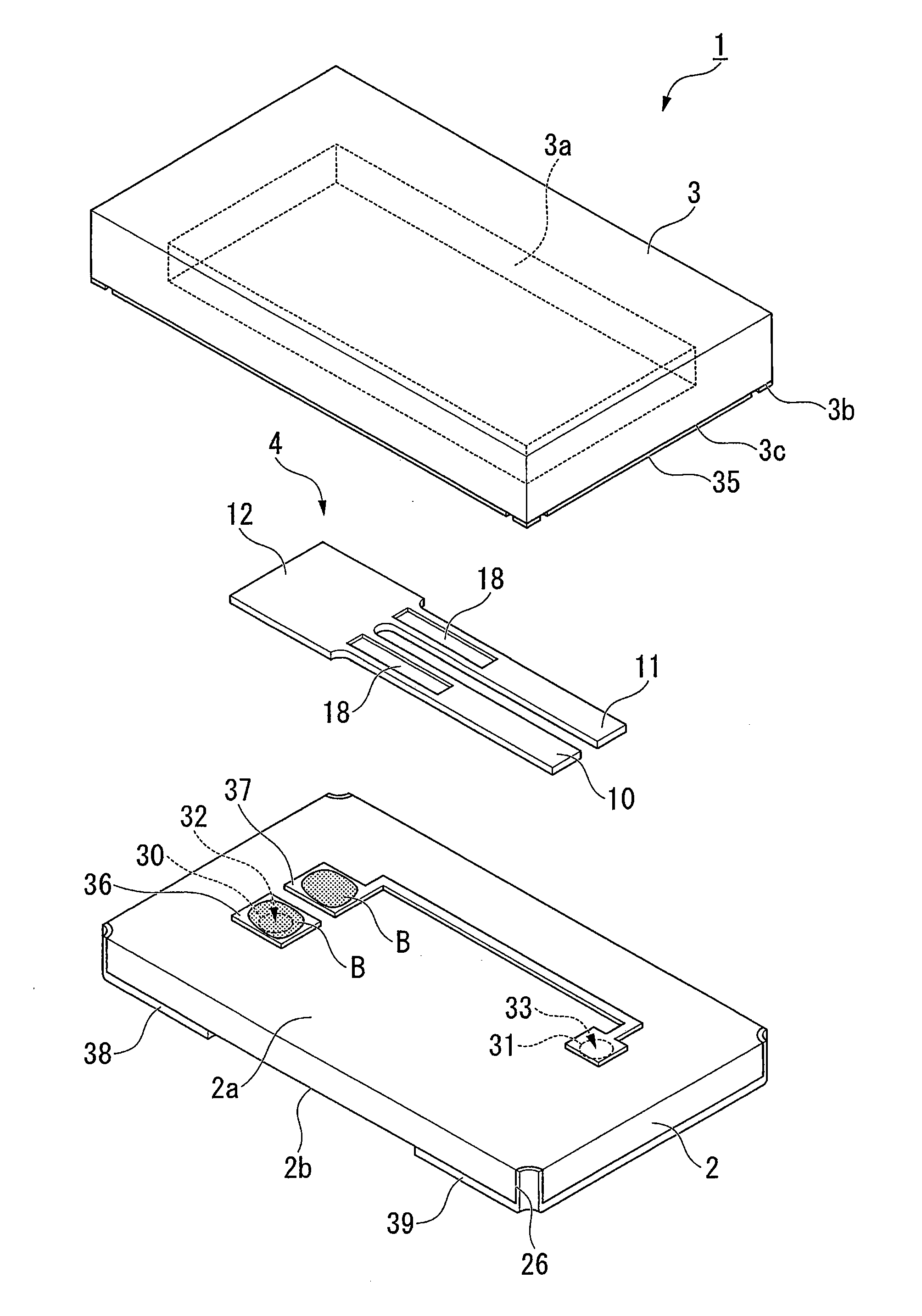
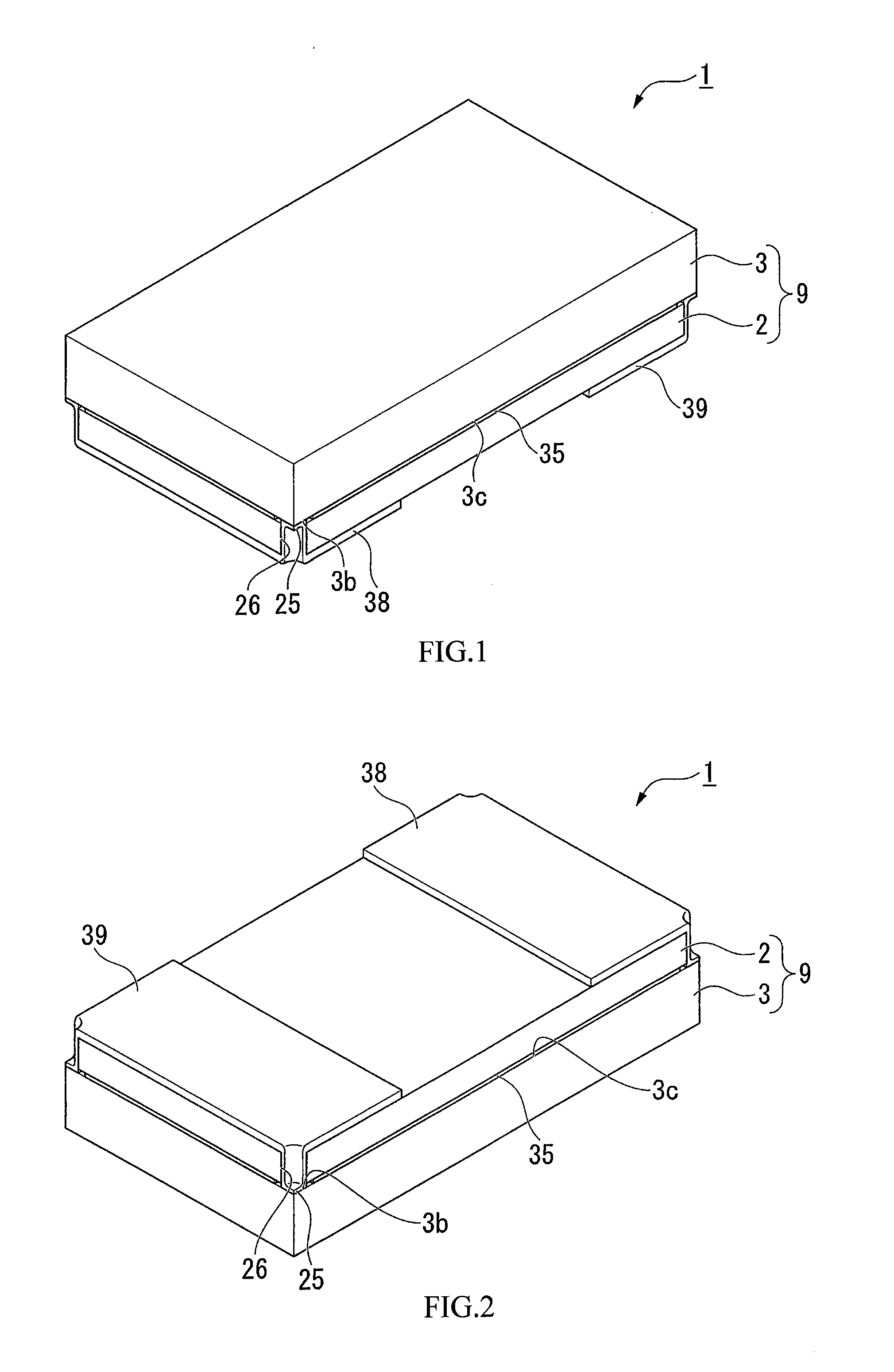
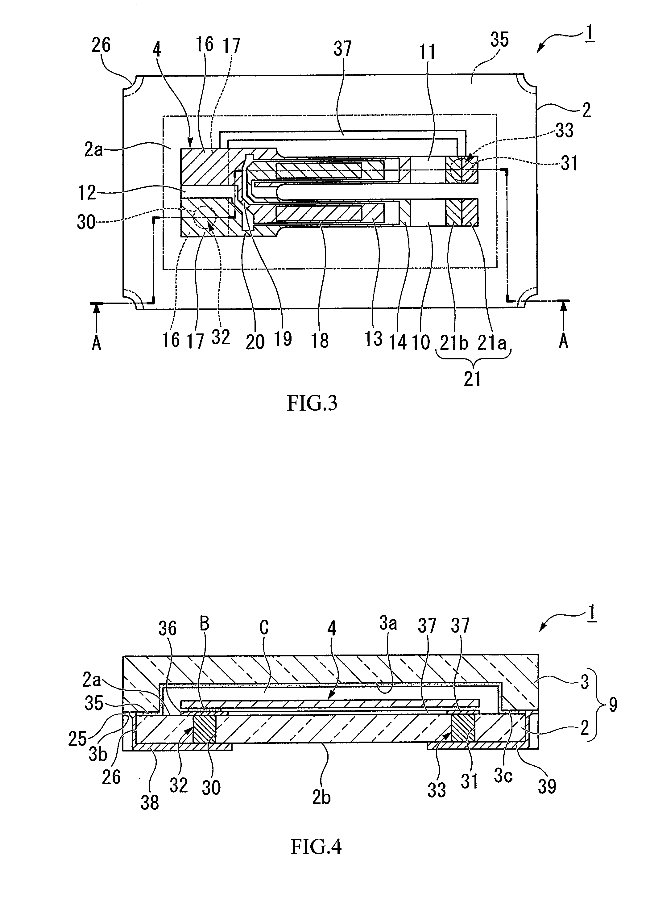
[0058]First, a piezoelectric vibrator according to the embodiment of the present invention will be described with reference to the drawings. FIG. 1 is a perspective view showing an external appearance of a piezoelectric vibrator according to an embodiment of the present invention as seen from the side of a lid substrate; and FIG. 2 is a perspective view showing an external appearance of the piezoelectric vibrator according to an embodiment of the present invention as seen from the side of a base substrate. Moreover, FIG. 3 is a top view of the piezoelectric vibrator, showing a state where the lid substrate is removed; FIG. 4 is a cross-sectional view of the piezoelectric vibrator taken along the line A-A in FIG. 3; and FIG. 5 is an exploded perspective view of the piezoelectric vibrator. In FIG. 5, for better understanding of the drawings, the illustration...


PUM

PropertyMeasurementUnit
central angleaaaaaaaaaa
voltage dropaaaaaaaaaa
frequencyaaaaaaaaaa

Abstract

Provided are a vacuum package and a method for manufacturing the vacuum package having excellent airtightness and capable of improving mounting strength, and a piezoelectric vibrator, an oscillator, an electronic device, and a radio-controlled timepiece. The package includes a base substrate and a lid substrate bonded to each other, a cavity formed between the base substrate and the lid substrate and configured to be capable of sealing a piezoelectric vibrating reed, and penetration electrodes penetrating through the base substrate in the thickness direction so as to make the inner side of the cavity and the outer side conductive. Portions of the base substrate and the lid substrate in the vicinity of the cavity form bonding regions in which the two substrates are bonded. A notch portion through which the bonding surface of the lid substrate is exposed as seen from the thickness direction of the base substrate is formed on the corner portions of the base substrate.

Description

RELATED APPLICATIONS[0001]This application claims priority under 35 U.S.C. §119 to Japanese Patent Application No. 2010-065126 filed on Mar. 19, 2010, the entire content of which is hereby incorporated by reference.BACKGROUND OF THE INVENTION[0002]1. Field of the Invention[0003]The present invention relates to a vacuum package, a method for manufacturing the vacuum package, a piezoelectric vibrator, and an oscillator, an electronic device, and a radio-controlled timepiece each having the piezoelectric vibrator.[0004]2. Description of the Related Art[0005]Recently, a piezoelectric vibrator (vacuum package) utilizing quartz or the like has been used in cellular phones and portable information terminals as the time source, the timing source of a control signal, a reference signal source, and the like. Although there are various piezoelectric vibrators of this type, a surface mounted device-type piezoelectric vibrator is known as one example thereof (for example, see JP-A-2002-124845).[...

Claims


Application Information

Patent Timeline
Patent Type & Authority Applications(United States)
IPC IPC(8): H01L41/053H01L41/08H03B1/00G04C11/02H01L41/22H01L23/02H10N30/88H03H3/02H03H9/02H03H9/10H10N30/00
CPCH03H9/02H03H9/1021Y10T29/42H03H2003/026H03H9/21
Inventor ARATAKE, KIYOSHI
Owner SII CRYSTAL TECH
Learn More