
Portable sensor device and patient monitor

a sensor device and patient technology, applied in the field of portable sensors, can solve the problems of increased error probability, increased stress on clinical personnel, incorrect diagnosis, etc., and achieve the effect of reducing the effort for data entry

Active Publication Date: 2011-09-15
PULSION MEDICAL SYSTEMS SE
View PDF6 Cites 7 Cited by
  • Summary
  • Abstract
  • Description
  • Claims
  • Application Information

AI Technical Summary

Benefits of technology

[0009]In view of the above problems, it is an object of the present invention to make available a portable sensor device and a related patient monitor, which reduce the effort for data entries.
[0010]According to the invention, this object is achieved by providing an additional channel provided, along with the channel for transmission of the data signal, for transmission of data between sensor device and patient monitor. In this connection, not only embodiments that allow transmission of data that go beyond the mere sensor signal from the sensor device to the patient monitor, but also embodiments that allow the transmission of data from the patient monitor to the sensor device, can be advantageous. These two embodiments in combination can be particularly advantageous.
[0011]Data entries on the patient monitor often serve for the interplay of patient monitor and sensor device. This interplay can be improved, according to the invention, not only by means of transmission of data that go beyond the mere sensor signal (for example a sensor type identifier or a calibration value) from the sensor device to the patient monitor, but also by means of transmission of data from the patient monitor to the sensor device.

Problems solved by technology

In the clinical use of portable sensor devices and related patient monitors of the type mentioned initially, problems can occur due to clinical personnel being put under additional stress as the result of having to enter, into the patient monitor, data that stand in connection with the use of the sensor device or are actually required for its use.
The time expenditure required for data entry and the accompanying distraction might often be tolerable, but generally, they increase the likelihood of error; this is the more the case, the more frequently the data entries need to be performed.
Incorrect data entries can furthermore lead to incorrect diagnosis results, if physiological parameters are normalized with an incorrect patient weight, for example.
If entry of comprehensive data into the patient monitor in question is required anew every time, the above problem is further intensified.

Method used


Image

  • Portable sensor device and patient monitor
  • Portable sensor device and patient monitor
  • Portable sensor device and patient monitor

Examples


Embodiment Construction

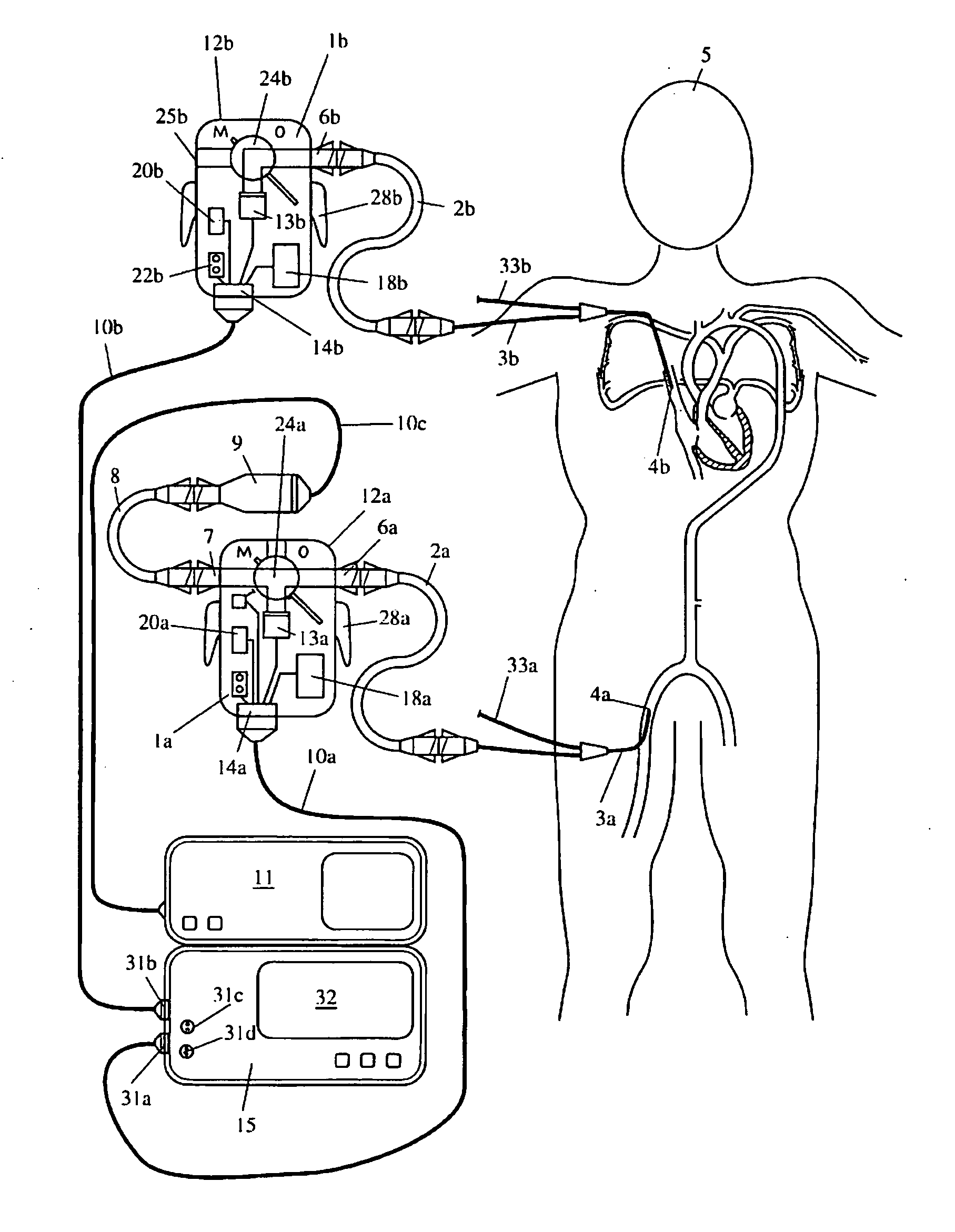
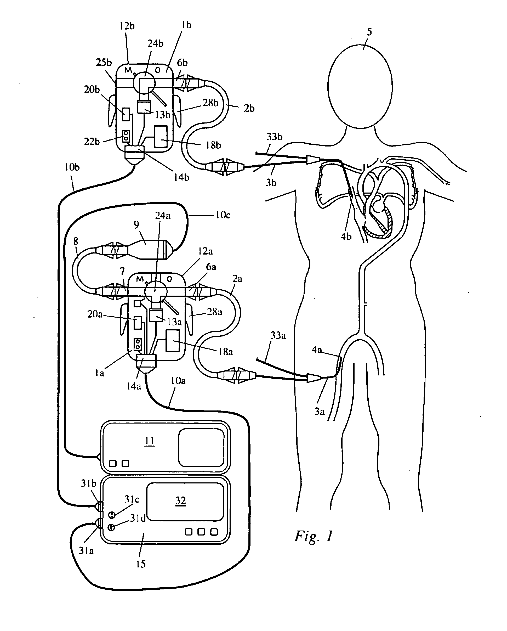
[0037]The portable sensor device 1a is connected with the arterial catheter 3a for measuring the arterial pressure at a measurement site 4a in the femoral artery of the patient 5, by way of a pressure hose 2a. The pressure hose 2a is connected with the sensor device 1a by way of the measurement site interface 6a, which is configured as a Luer lock connection. The electronic pressure sensor 13a is accommodated in the sensor housing 12a of the sensor device 1a. The analog sensor signal of the pressure sensor 13a is output to the patient monitor 15 by way of a cable 10a connected with the patient monitor interface 14a.

[0038]Aside from the channel 16 for the analog sensor signal, additional channels are provided for communication between sensor device 1a and patient monitor 15. A bidirectional channel 17 serves for writing to and querying the memory module 18a, in which patient data can be stored. By way of the identification channel 19, an identification signal can be read out by the ...


PUM


Abstract

The portable sensor device is connected with the arterial pressure measurement catheter by way of a pressure hose. The electronic pressure sensor is accommodated in the sensor housing. The analog sensor signal is output to the patient monitor by way of a cable. Aside from the channel for the analog sensor signal, additional channels are provided for communication between sensor device and patient monitor. A bidirectional channel serves for writing to and querying the memory module, in which patient data, such as age, gender, height / weight, etc., can be stored. The three-way cock possesses the settings “M” (measurement operation) and “0” (calibration measurement), in which the contactor is brought into connection with the contact. The switching contact is transmitted to the patient monitor, which thereby automatically recognizes zeroing of the sensor.

Description

CROSS REFERENCE TO RELATED APPLICATIONS[0001]Applicants claim priority under 35 U.S.C. 119 of German Application No. 10 2010 010 610.0 filed Mar. 8, 2010, the disclosure of which is incorporated by reference.BACKGROUND OF THE INVENTION[0002]The present invention relates to a portable sensor device, particularly a portable sensor device that comprises an electronic sensor component for measuring a physiological variable at a measurement site of the body of a patient, a measurement site interface for connecting the electronic sensor component to measurement site connection means for establishing a measurement connection between the electronic sensor component and the measurement site, a patient monitor interface for connecting the electronic sensor component to patient monitor connection means for establishing a signal connection between the electronic sensor component and the patient monitor, and a sensor housing for accommodating the electronic sensor component, the measurement site...

Claims


Application Information

Patent Timeline
IPC IPC(8): A61B5/05
CPCA61B5/02156A61B2560/0456A61B2560/0431A61B5/02158A61B5/00A61B5/021A61B5/02141A61B5/023A61B8/04
Inventor STEINER, CHRISTIANGUTZLER, DOMINIKVEECK, MARCUSSCHEIER, JOERGMANEGOLD, CHRISTOPH
Owner PULSION MEDICAL SYSTEMS SE
Learn More