
Light conversion efficiency-enhanced solar cell fabricated with downshifting nanomaterial

a solar cell and nanomaterial technology, applied in the field of solar cell devices, can solve the problems of high cost of electricity from silicon solar cells, material disadvantages, and high cost of electricity from these solar cells, and achieve the effect of increasing the light conversion efficiency of solar cells

Inactive Publication Date: 2011-09-15
PACIFIC LIGHT TECH
View PDF0 Cites 63 Cited by
  • Summary
  • Abstract
  • Description
  • Claims
  • Application Information

AI Technical Summary

Benefits of technology

[0011]The light conversion efficiency of a solar cell can be increased by employing a downshifting nanomaterial to supplement the activity of a photovoltaic material.
[0015]In some embodiments, the solar cell platform is modified to enhance collection or absorption of wavelength-specific photons within the downshifting material at the expense of absorption of the same wavelength-specific photons within the solar cell platform.
[0024]In some embodiments, a solar cell employing a downshifting material is used as a low cost rooftop device.
[0025]In some embodiments, enhanced efficiency provided by the optical downshifting layer permits advantageous modifications to the solar cell platform that enhances its efficiency as well.

Problems solved by technology

However, the cost of electricity from these silicon solar cells is still higher in dollar per watt than most currently available retail peak electricity rates.
Dyes also typically have a very large overlap between their absorption and emission spectrum, such that self-absorption losses are significant.
These materials also have disadvantages.

Method used


Image

  • Light conversion efficiency-enhanced solar cell fabricated with downshifting nanomaterial
  • Light conversion efficiency-enhanced solar cell fabricated with downshifting nanomaterial
  • Light conversion efficiency-enhanced solar cell fabricated with downshifting nanomaterial

Examples


Embodiment Construction

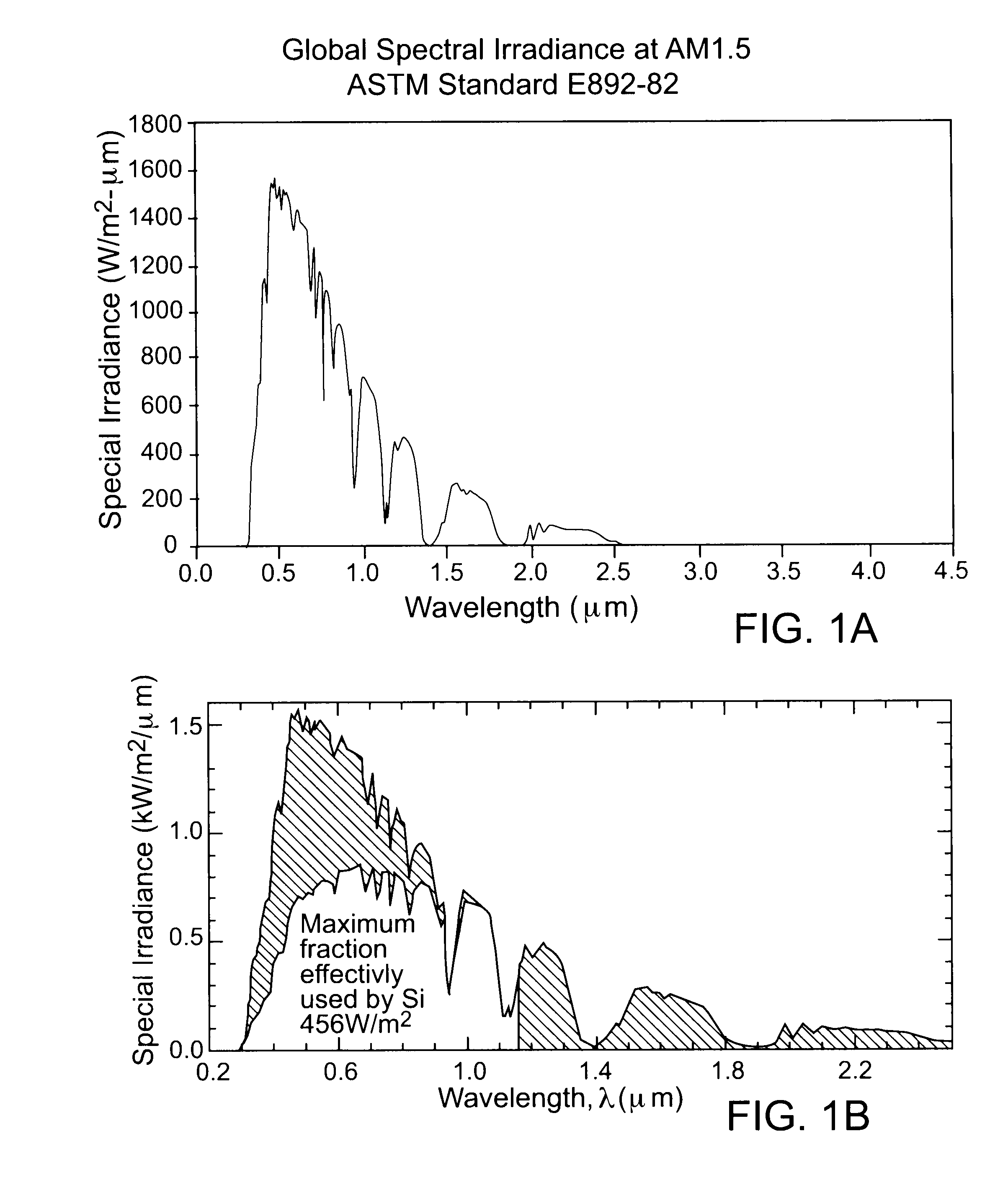
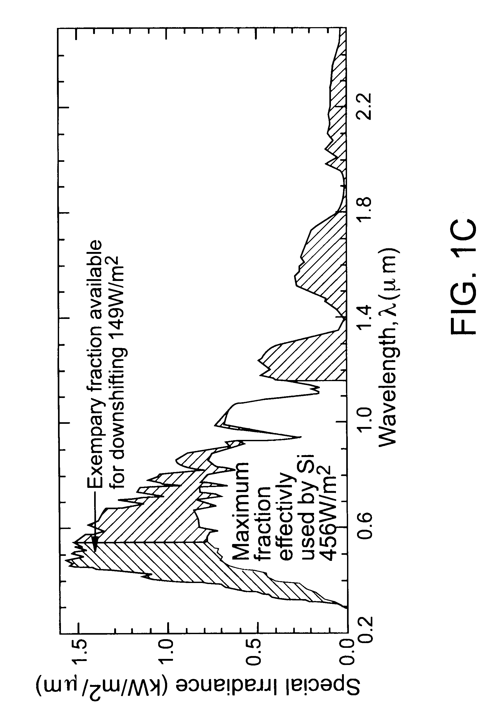
[0039]Within the fixed portion spectral irradiance from the Sun, silicon has a region of light conversion activity from about 0.3 micron to about 1.2 microns due to the 1.1 eV band gap of silicon for absorbing incident photons and generating electron and hole charge carriers, as shown in FIG.1B. For silicon, this region is characterized at least in part by a primary light absorption spectrum from about 0.6 micron to about 1 micron, in which silicon effectively absorbs photons and generates electron and hole charge carriers. FIG. 1B shows, however, that silicon is far less effective at absorbing sunlight in about the 0.2 micron to almost 0.6 micron spectral region. Other photovoltaic materials exhibit areas of the spectral region that are less effective at absorbing sunlight than in their respective primary light absorption spectra.

[0040]For a typical solar cell platform using conventional photovoltaic material and having a limited primary light absorption spectrum, the efficiency of...


PUM


Abstract

The light conversion efficiency of a solar cell (10) is enhanced by using an optical downshifting layer (30) in cooperation with a photovoltaic material (22). The optical downshifting layer converts photons (50) having wavelengths in a supplemental light absorption spectrum into photons (52) having a wavelength in the primary light absorption spectrum of the photovoltaic material. The cost effectiveness and efficiency of solar cells platforms (20) can be increased by relaxing the range of the primary light absorption spectrum of the photovoltaic material. The optical downshifting layer can be applied as a low cost solution processed film composed of highly absorbing and emissive quantum dot heterostructure nanomaterial embedded in an inert matrix to improve the short wavelength response of the photovoltaic material. The enhanced efficiency provided by the optical downshifting layer permits advantageous modifications to the solar cell platform that enhances its efficiency as well.

Description

RELATED APPLICATION[0001]This application claims the benefit under 35 U.S.C. §119(e) of U.S. Provisional Patent Application No. 61 / 225,472, filed Jul. 14, 2009.COPYRIGHT NOTICE[0002]© 2010 Spectrawatt, Inc. A portion of the disclosure of this patent document contains material that is subject to copyright protection. The copyright owner has no objection to the facsimile reproduction by anyone of the patent document or the patent disclosure, as it appears in the Patent and Trademark Office patent file or records, but otherwise reserves all copyright rights whatsoever. 37 CFR §1.71(d).TECHNICAL FIELD[0003]This disclosure relates to solar cell devices and, in particular, to a solar cell having a photoabsorptive nanomaterial layer that downshifts certain wavelengths of incident light into a wavelength region that is better absorbed by the photovoltaic material of the solar cell.BACKGROUND INFORMATION[0004]“First generation” solar cells are based on the use of crystalline silicon as the p...

Claims


Application Information

Patent Timeline
IPC IPC(8): H01L31/0232H01L31/0224
CPCH01L31/055Y02E10/52Y02E10/542C09K11/565C09K11/02
Inventor KURTIN, JUANITA N.GUICHARD, ALEX R.HUGHES, STEVEN M.MAYER, ALEX C.PARK, OUN HOSCULLY, SHAWN R.TRUDEAU, PAUL-EMILE B.REESE, COLIN C.SHEORAN, MANAVMASSON, GEORGETA
Owner PACIFIC LIGHT TECH
Learn More