
Gas engine

a gas engine and gas technology, applied in the direction of electric ignition installation, machines/engines, mechanical equipment, etc., can solve the problem of poor condition of the seat surface between, and achieve the effect of reducing the manufacturing cost of the first and second check valves

Active Publication Date: 2011-09-08
MITSUBISHI HEAVY IND ENGINE & TURBOCHARGER LTD
View PDF15 Cites 24 Cited by
  • Summary
  • Abstract
  • Description
  • Claims
  • Application Information

AI Technical Summary

Benefits of technology

The present invention relates to a gas engine with a spark plug and a solenoid valve. The technical effects of the invention include preventing the adhesion of soot to the solenoid valve and reducing the loss of fuel due to dead volume. The gas engine includes a fuel inlet connecting piece and a first check valve to prevent the combustion gas from flowing backwards in the pre-combustion chamber. The first check valve is positioned just after the fuel inlet connecting piece and the solenoid valve, and a second check valve is provided in the fuel passage in the mounting hardware piece. These features protect the solenoid valve from soot and malfunctions caused by soot.

Problems solved by technology

The soot deposit often causes the adhesion of the check valve toward the fitting component thereof or the adhesion of the seat thereof; and, the soot deposit often causes the poor condition of the seat surface between the check valve and the bearing component thereof.
The soot deposit often causes the adhesion of the check valve toward the fitting component thereof or the adhesion of the seat thereof; further, the soot tends to cause the adhesion of the solenoid valve or the deterioration of the poor seat conditions as to the check valve and the solenoid valve.
Further, it is required to pay attention to the loss due to the dead volume in the fuel inlet passage; hereby, the dead volume means unnecessary space to supply the fuel gas of the prescribed fuel flow rate, into the pre-combustion chamber.

Method used


Image

  • Gas engine
  • Gas engine
  • Gas engine

Examples


Embodiment Construction

[0039]Hereafter, the present invention will be described in detail with reference to the embodiments shown in the figures. However, the dimensions, materials, shape, the relative placement and so on of a component described in these embodiments shall not be construed as limiting the scope of the invention thereto, unless especially specific mention is made.

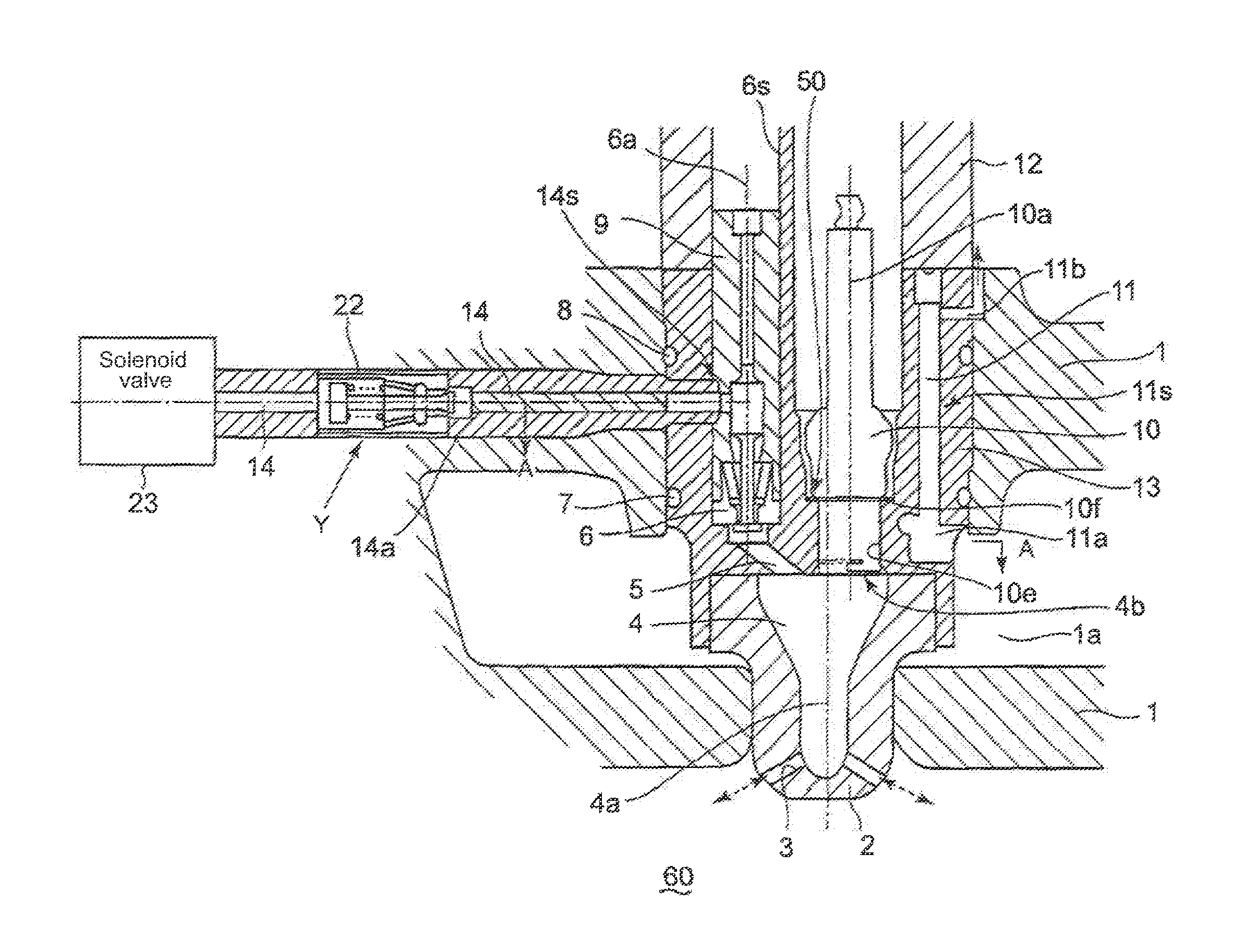
[0040]FIG. 1 shows a cross-section of a gas engine provided with a spark plug, according to an embodiment of the present invention, the cross-section including the vertical center axis of a pre-combustion chamber provided in the gas engine; FIG. 2 shows A-A cross-section of FIG. 1.

[0041]In FIG. 1, a pre-combustion chamber mouthpiece (a pre-combustion chamber mouthpiece) 2 is fastened to and on the bottom wall of a cylinder head 1, the pre-combustion chamber mouthpiece being surrounded by a water chamber 1a; and, a pre-combustion chamber 4 is formed inside the pre-combustion chamber mouthpiece. A mounting hardware piece 13 for hous...


PUM


Abstract

Provided is a gas engine having a spark plug provided with a pre-combustion chamber and a check valve, the gas engine, in which the check valve is arranged in the neighborhood of the pre-combustion chamber, being capable of preventing adhesion of a solenoid controlled valve provided at an upstream side of the check valve due to soot accumulation, and dead volume in a fuel inlet passage. In a gas engine in which fuel gas is supplied to the pre-combustion chamber through the fuel gas inlet passage and the fuel gas supplied in the pre-combustion chamber is ignited by spark discharge at the spark plug that is fitted to a mounting hardware piece via a seat surface, a solenoid valve for performing open-close control of the fuel gas is provided, and a first check valve is also provided posterior to a discharge side of the solenoid valve so as to prevent back flow of the combustion gas from the pre-combustion chamber to the solenoid controlled valve.

Description

BACKGROUND OF THE INVENTION[0001]1. Field of the Invention[0002]The present invention is applied to a gas engine provided with a spark plug; thereby, fuel gas is supplied to a pre-combustion chamber through a fuel gas inlet passage and the fuel gas supplied in the pre-combustion chamber is ignited by the spark discharge at the spark plug that is fitted on a seat surface in a mounting hardware piece for housing the spark plug.[0003]2. Background of the Invention[0004]FIG. 4 shows a cross-section around a pre-combustion chamber 4 of a conventional gas engine provided with a spark plug, the cross-section including the vertical center axis of the pre-combustion chamber.[0005]In FIG. 4, a pre-combustion chamber mouthpiece 2 is fastened to and on the bottom wall of a cylinder head 1, the pre-combustion chamber mouthpiece being surrounded by a water chamber 1a; and, a pre-combustion chamber 4 is formed inside the pre-combustion chamber mouthpiece.[0006]A mounting hardware piece 13 for hous...

Claims


Application Information

Patent Timeline
Patent Type & Authority Applications(United States)
IPC IPC(8): F02B19/12
CPCF01P3/16F02B19/1009F02B19/108F02B19/12F02F1/243F02M21/0233F02M21/0242F02M21/0254F02M21/0269F02M21/0275F02P13/00Y02T10/12Y02T10/30
Inventor ISHIDA, MICHIYASUMAEHATA, KIMIHIKO
Owner MITSUBISHI HEAVY IND ENGINE & TURBOCHARGER LTD
Learn More