Eureka AIR delivers breakthrough ideas for toughest innovation challenges, trusted by R&D personnel around the world.

Building with integrated natural systems

a natural system and building technology, applied in the field of buildings, can solve the problems of inability to increase the amount of solar panels used to produce power, and inability to meet the needs of building owners, etc., to achieve optimal sunlight capture, shading or reflection, and reduce forced air requirements

Inactive Publication Date: 2011-09-08
MICHAEL FULLER ARCHITECTS PC
View PDF89 Cites 40 Cited by
  • Summary
  • Abstract
  • Description
  • Claims
  • Application Information

AI Technical Summary

Benefits of technology

[0013]The inner wall of the dual exterior cover construction comprises the structural exterior of the living space of the building. The gap between the inner walls and the exterior cover is available as a greenhouse space to cultivate plants. This greenhouse space also serves as an insulating barrier for more efficient regulation of the temperature within the living space.
[0017]Air is allowed to circulate through the interior habitable space, and may be vented into the greenhouse space. Air within the green house space may be circulated by one or more mechanical fans. Air is evacuated from the building through vents located near the apexes of the exterior cover. A natural circulation pattern develops as air is warmed in the greenhouse space such that an upward circulation or flow is created. Accordingly, forced air requirements are reduced as compared to most traditional building spaces.
[0018]The exterior cover construction includes a relatively thin film of transparent or translucent material, such as a polymer which can be molded into a desired shape. One example of a polymer that can be used includes ethylenetetraflowro-ethylene (ETFE). The exterior cover or skin is supported by an underlying aluminum frame which generally conforms to the shape of the exterior cover / skin. The aluminum frame provides adequate support against loading conditions such as wind / snow. Although relatively thin and transparent, the skin provides protection for the interior structure. Vents are located in the apex of the exterior cover / skin as mentioned in order to allow a continual circulation of air through the greenhouse space.
[0019]The louvers are mounted to the exterior cover so that the louvers can be rotated along at least one axis in order to track the path of the sun, or otherwise provide the ability to adjustably place the louvers for optimal sunlight capture, shading, or reflection of light into the interior structure.
[0023]Planter boxes and planting platforms may be attached at each floor level as by steel beams that extend beyond the concrete floor slabs. A drip irrigation system can also be provided to water the planted areas, and this drip irrigation system uses collected rainwater stored in the well. A relatively large garden area may be provided on the roof of the interior structure, and may be referred to as an arboretum. The arboretum is also structurally supported by reinforced steel beams located on the roof and capable of carrying the additional weight of the soil that is used for planting. A waterproof liner is used to keep the lower levels dry in the event the structure is built with multiple floors.

Problems solved by technology

In most cases, the solar panels are mounted on the roof of the building, and therefore are limited in terms of the amount of solar panels that can be used to produce power.
When land is available, an increased number of solar panel arrays can be situated at a location adjacent the building(s) to be powered, however increasing solar panels in this manner is not a viable solution for powering buildings within most cities.

Method used


Image

  • Building with integrated natural systems
  • Building with integrated natural systems
  • Building with integrated natural systems

Examples


Embodiment Construction

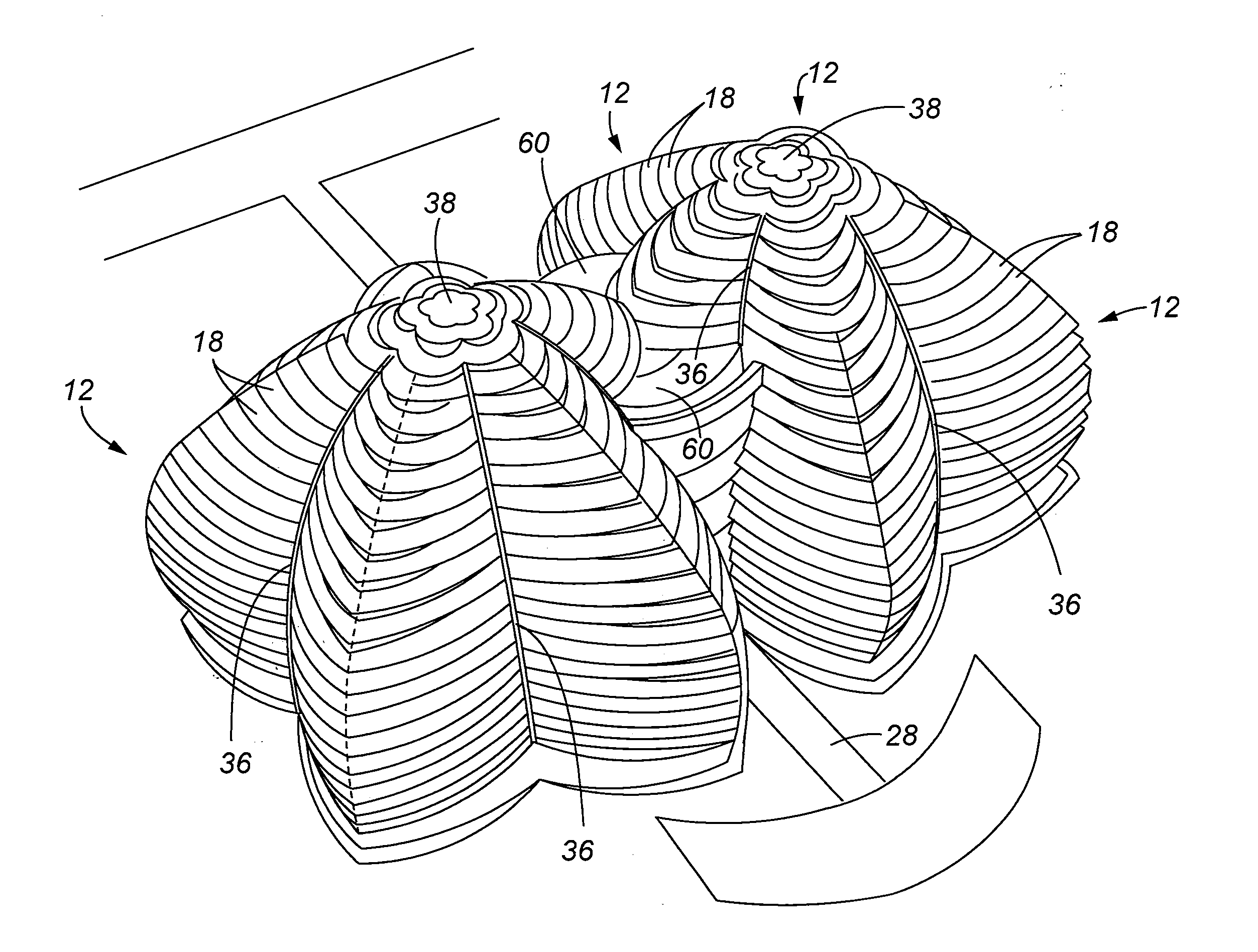
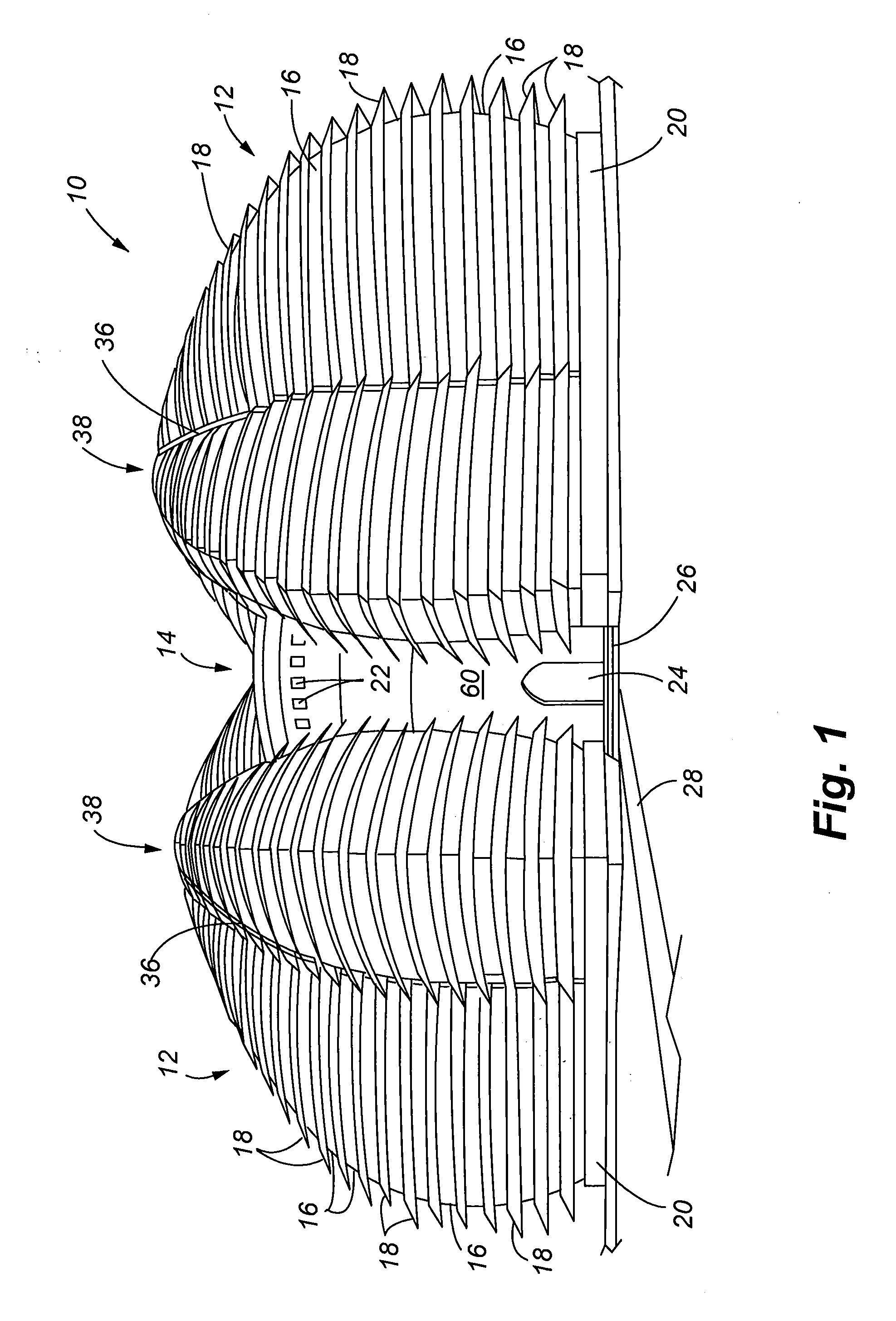
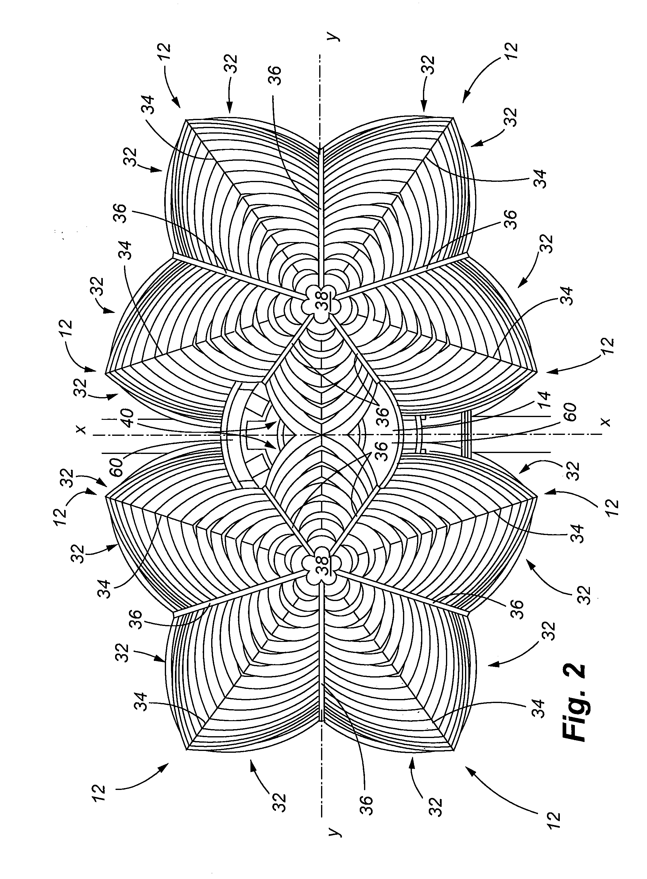
[0035]FIGS. 1-3 illustrate the building with the integrated natural systems in accordance with a preferred embodiment of the present invention. The building 10 is characterized as a complex-shaped structure having a plurality of curved exterior sections 12. Each of the curved exterior sections 12 include a pair of symmetrical extensions 32 that are joined along a crest or ridge line 34. The building is further characterized as having two groups of the curved exterior sections 12 interconnected by a pair of central facing curved exterior sections 40, as best seen in FIG. 2. The curved exterior sections 12 are connected to one another in a circumferential fashion and are joined along receding areas or troughs. Rain collection gutters 36 are located in these receding areas. When viewed as from the plan view of FIG. 2, the two groups of exterior sections 12 each form shapes that have a center or apex 38. As shown from the plan view of FIG. 2, the rain collection gutters 36 each extend r...


PUM


Abstract

A building is provided with integrated natural systems that reduce dependency on external resources to operate and maintain the building. A source of electricity is provided through an extensive set of solar panels that may be incorporated on louvers mounted to the exterior of the building. The building has a double insulative layer to include an outer airtight membrane or cover, and an internal building structure that defines habitable space within the structure. Rainwater may be collected and stored within a subsurface well. The space between the internal structure and outer membrane may support the growth of vegetation in a greenhouse environment. A flow of temperature regulated air is provided through the structure by a set of underground pipes in which the air is circulated through a central core of the building, into the habitable space, and then outward into the greenhouse space.

Description

FIELD OF THE INVENTION[0001]The present invention relates to buildings that incorporate natural systems to cool, heat, ventilate, collect and purify water, and generate power for operation of the building. More particularly the invention relates to a building that integrates these natural systems in a sustainable, functional and economical manner.BACKGROUND OF THE INVENTION[0002]The use of solar power has become quite common as a means to provide power for man-made structures to include both residential and commercial buildings. With the increased cost of energy from traditional sources such as fossil fuels, coupled with a transition in industry towards eco-friendly or “green” technologies, building architectures and designs continue to evolve to incorporate solar power systems.[0003]Solar panel arrays are often installed on existing buildings. In most cases, the solar panels are mounted on the roof of the building, and therefore are limited in terms of the amount of solar panels th...

Claims


Application Information

Patent Timeline
Patent Type & Authority Applications(United States)
IPC IPC(8): E04H14/00E04D13/18E04F17/00
CPCE04F17/00E04B2001/0053E04H1/04E04H14/00
Inventor FULLER, MICHAEL B.
Owner MICHAEL FULLER ARCHITECTS PC
Why Eureka
Eureka Blog
Learn More