Signal transmitting device and signal transmitting method
a signal transmitting device and signal technology, applied in the direction of signal generators with optical-mechanical scanning, television systems, color signal processing circuits, etc., can solve the problems of not being able to transmit signals, power consumption of broadcasting cameras, and inability to propose bayer structures, etc., to achieve the effect of improving convenien
Inactive Publication Date: 2011-09-01
SONY CORP
View PDF7 Cites 3 Cited by
- Summary
- Abstract
- Description
- Claims
- Application Information
AI Technical Summary
Benefits of technology
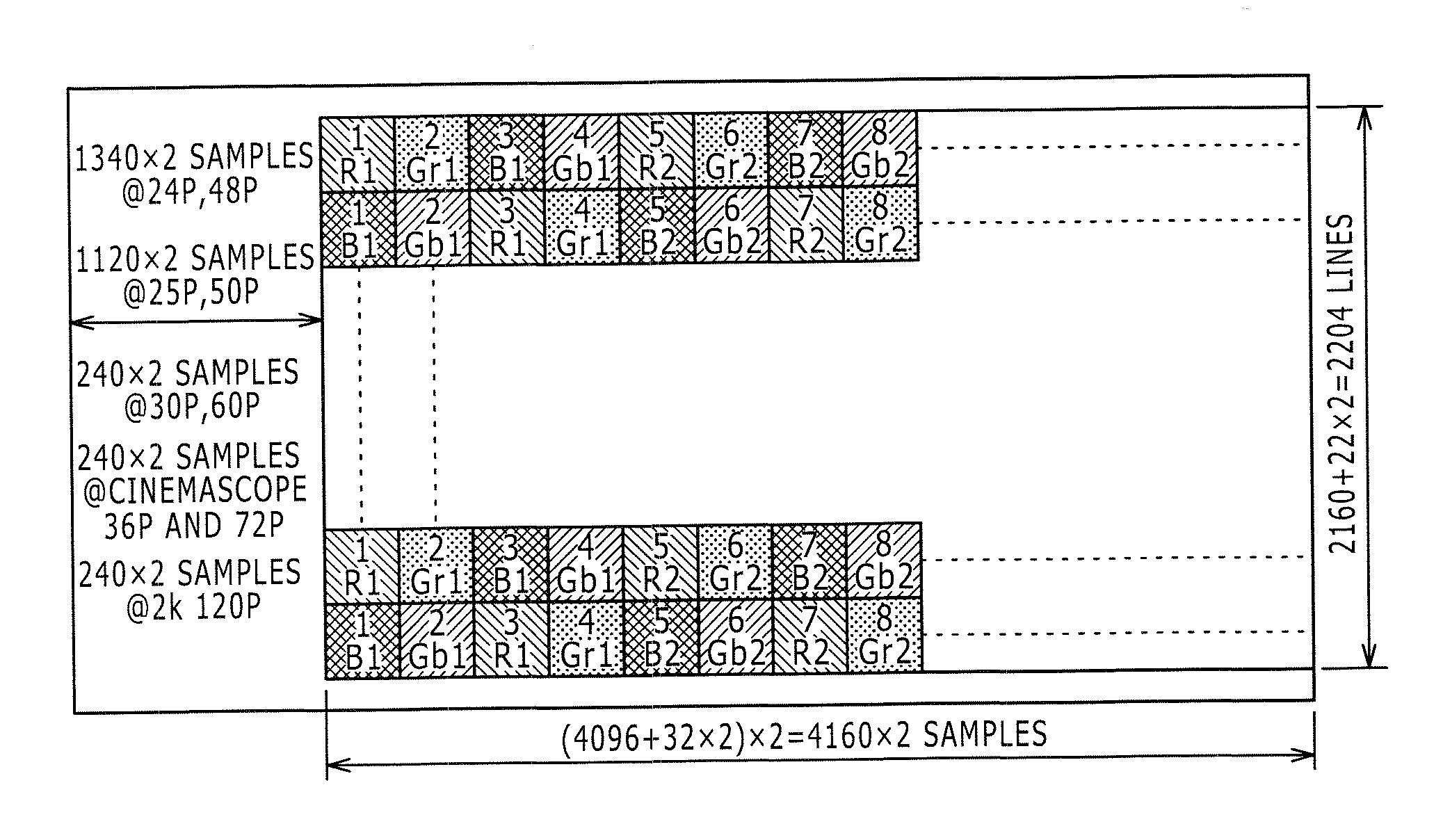
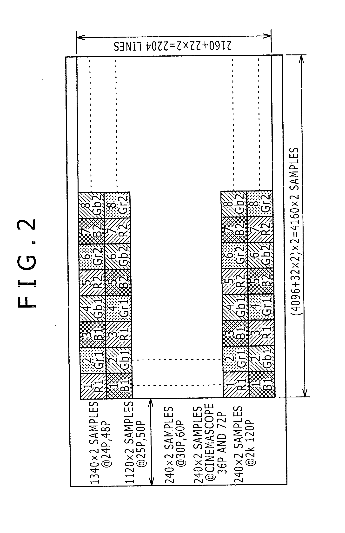
[0025]According to the present invention, a B / R ch is generated by alternately multiplexing image signals read from B pixels and R pixels among video signals received from an image pickup element of the double density Bayer structure in an active region corresponding to a C ch in HD-SDI. In addition, a G ch is generated by multiplexing, in order, image signals read from G pixels in an active region corresponding to a Y ch in HD-SDI. Thus, image signals can be transmitted in a data format similar to the transmission format of conventional HD-SDI. In addition, traditionally used transmission lines can be used without new transmission lines being provided, so that an effect of improving convenience is obtained.
Problems solved by technology
Thus, with increases in the number of pixels, the power consumption of the broadcasting camera is also increasing.
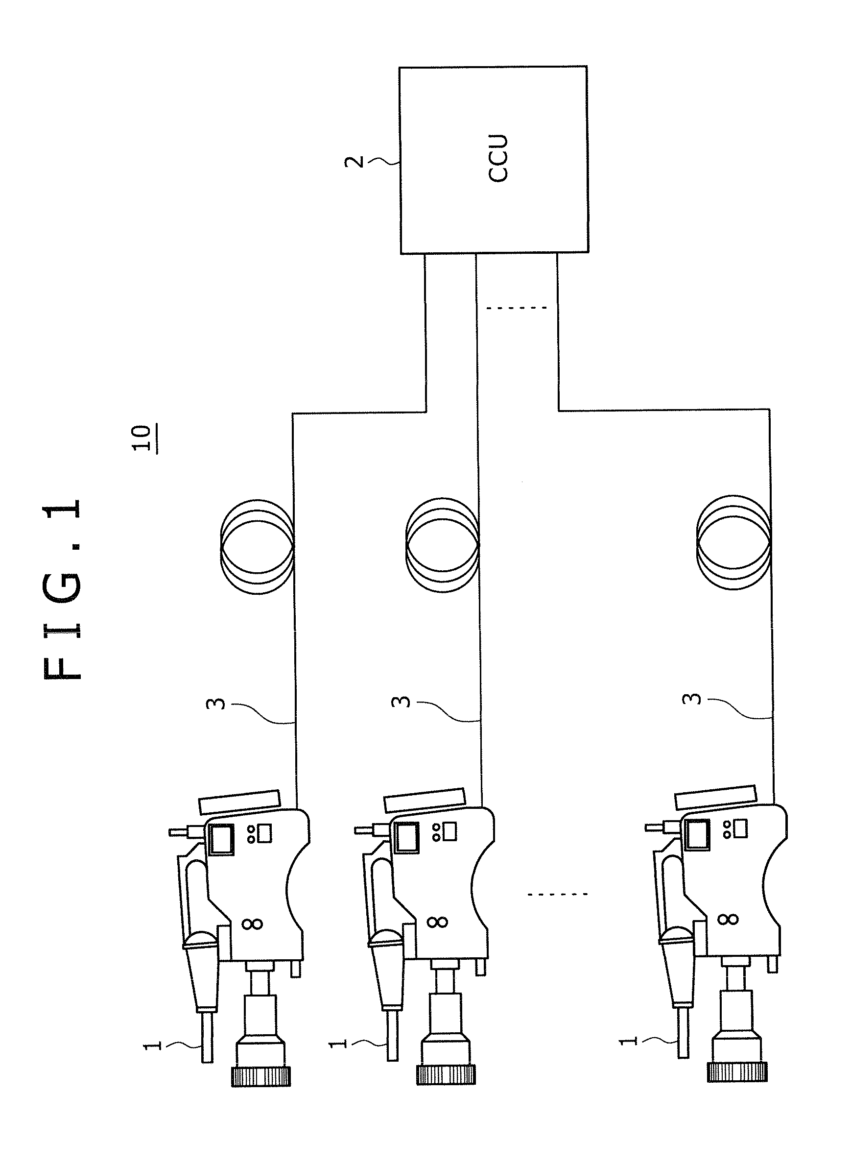
However, an interface or an interface data structure for transmitting a video signal received from an image pickup element of the double density Bayer structure has not been proposed.
Therefore the signal cannot be transmitted.
Method used
View moreImage
Smart ImageViewing Examples
Examples
first embodiment (
1. First Embodiment (Example of Transmitting Double Density Bayer 4 k / 23.98 P-30 P / 16-Bit Signal at 5.94 Gbps on 2 Ch Using 8B / 10B Code)
second embodiment (
2. Second Embodiment (Example of Transmitting Double Density Bayer 4 k / 47.95 P-60 P / 16-Bit Signal at 5.94 Gbps on 4 Ch Using 8B / 10B Code)
third embodiment (
3. Third Embodiment (Example of Transmitting Double Density Bayer 4 k / 23.98 P-30 P / 16-Bit Signal at 10.692 Gbps on 1 Ch Using 8B / 10B Code and Scramble)
Login to View More PUM
 Abstract
Disclosed herein is a signal transmitting device including a multiplexing section configured to generate a B / R ch by alternately multiplexing image signals read from B pixels and R pixels among image signals read and input in units of a predetermined number of samples in each of the first line and the second line from said image pickup element in an active region corresponding to a C ch in HD-SDI together with start code of one of SAV and EAV, and generate a G ch by multiplexing, in order, image signals read from G pixels in an active region corresponding to a Y ch in HD-SDI together with said start code; and an 8B / 10B encoder configured to output serial digital data converted by 8B / 10B-encoding the active regions on the B / R ch and the G ch having data structures corresponding to said HD-SDI and an auxiliary data region including SAV, EAV, LN, and CRCC.
Description
BACKGROUND OF THE INVENTION[0001]1. Field of the Invention[0002]The present invention relates to a signal transmitting device and a signal transmitting method suitable for application to a case of transmitting an image signal output from an image sensor of a double density Bayer structure, for example.[0003]2. Description of the Related Art[0004]In the past, development of receiving systems and image pickup systems for ultrahigh resolution video signals surpassing an HD (High Definition) signal as a current image signal (video signal) in which one frame is 1920 samples×1080 lines is underway. For example, UHDTV (Ultra High Definition TV) standards as a next-generation broadcasting system having 4 times or 16 times the number of pixels of current HD are being established by international societies. The international societies include the ITU (International Telecommunication Union) and SMPTE (Society of Motion Picture and Television Engineers).[0005]Video standards proposed to the ITU...
Claims
Login to View More Application Information
Patent Timeline
 IPC IPC(8): H04N11/22
CPCH04N5/225H04N9/045H04N5/23203H04N23/66H04N23/00H04N23/60H04N23/84H04N25/134
Inventor YAMASHITA, SHIGEYUKI
Owner SONY CORP
Features
- R&D
- Intellectual Property
- Life Sciences
- Materials
- Tech Scout
- Unparalleled Data Quality
- Higher Quality Content
- 60% Fewer Hallucinations
Learn More Browse by: Latest US Patents, China's latest patents, Technical Efficacy Thesaurus, Application Domain, Technology Topic, Popular Technical Reports.
© 2025 PatSnap. All rights reserved.Legal|Privacy policy|Modern Slavery Act Transparency Statement|Sitemap|About US| Contact US: help@patsnap.com


