
Asynchronous Power Generator for a Wind Turbine

Active Publication Date: 2011-09-01
SIEMENS GAMESA RENEWABLE ENERGY AS
View PDF6 Cites 4 Cited by
  • Summary
  • Abstract
  • Description
  • Claims
  • Application Information

AI Technical Summary

Benefits of technology

[0013]An asynchronous power generator for a wind turbine comprises a voltage supply and a stator with at least one stator coil supplied with an alternating voltage by the voltage supply, characterized in that the voltage supply is configured to adjust the voltage supplied to the stator coil based on the output power generated by the wind turbine for reducing noise from the asynchronous power generator.
[0015]Since the intensity of the emitted sound will increase with the increasing magnitude of the supplied voltage, a proper adjustment of the voltage supplied to the stator coils reduces the emitted sound and thus achieves the object of the present invention. In particular, the adjustment of the power supplied to the stator coils is made dependent on the output power generated by the wind turbine. Thus, the present generator is enabled to adapt the supplied voltage to the current level of power, so that an optimum power output can be established even when reducing the magnitude of voltage supplied to the stator coils.
[0016]Thus, while establishing optimum output power, the present invention may reduce the supplied voltage, which in turn will lead to a reduction in the magnitude of the flux in the stator core laminate and therefore will reduce the vibrations of the active stator parts, leading to a substantial noise reduction.
[0025]Thus, a method is given for use with the asynchronous generator that provides for the technical effects presented by the generator or any one of its embodiments, particularly when the voltage supply, or other of the functional components of the generator, are configured to execute the method steps.

Problems solved by technology

Such vibration, however, produces a sound having the frequency of the alternating voltage supplied to the stator coils.
Particularly when used with wind turbines, the sound thus produced by the asynchronous generators is often found irritating by people in the immediate vicinity of the wind turbine, for instance by people living next to a wind turbine or a wind turbine park.
In order to reduce the noise thus generated by wind turbines, systems of the state of the art use noise reducing cladding for the generator housing of the wind turbine, which leads to increased material cost and additional technical effort in the manufacturing of wind turbines.

Method used


Image

  • Asynchronous Power Generator for a Wind Turbine
  • Asynchronous Power Generator for a Wind Turbine
  • Asynchronous Power Generator for a Wind Turbine

Examples


Embodiment Construction

oil of a stator of the asynchronous power generator, based on the determined output power.

[0025]Thus, a method is given for use with the asynchronous generator that provides for the technical effects presented by the generator or any one of its embodiments, particularly when the voltage supply, or other of the functional components of the generator, are configured to execute the method steps.

BRIEF DESCRIPTION OF THE DRAWINGS

[0026]The invention will be described in more detail below, referring to the following figures:

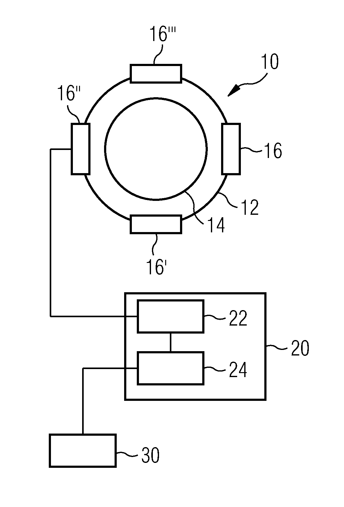
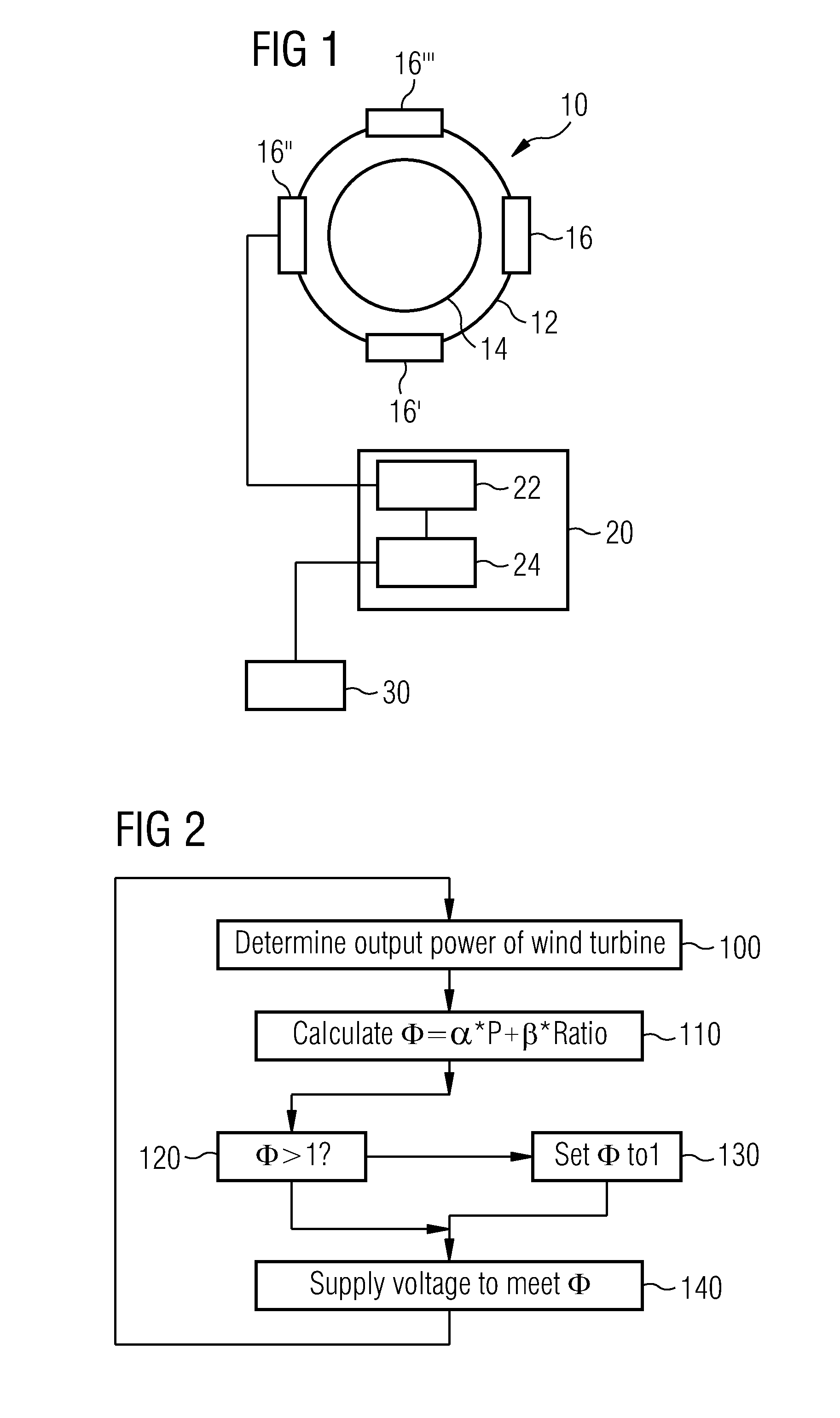
[0027]FIG. 1 shows a schematic overview of an embodiment of the asynchronous generator;

[0028]FIG. 2 shows a schematic overview of an embodiment of the method of voltage control;

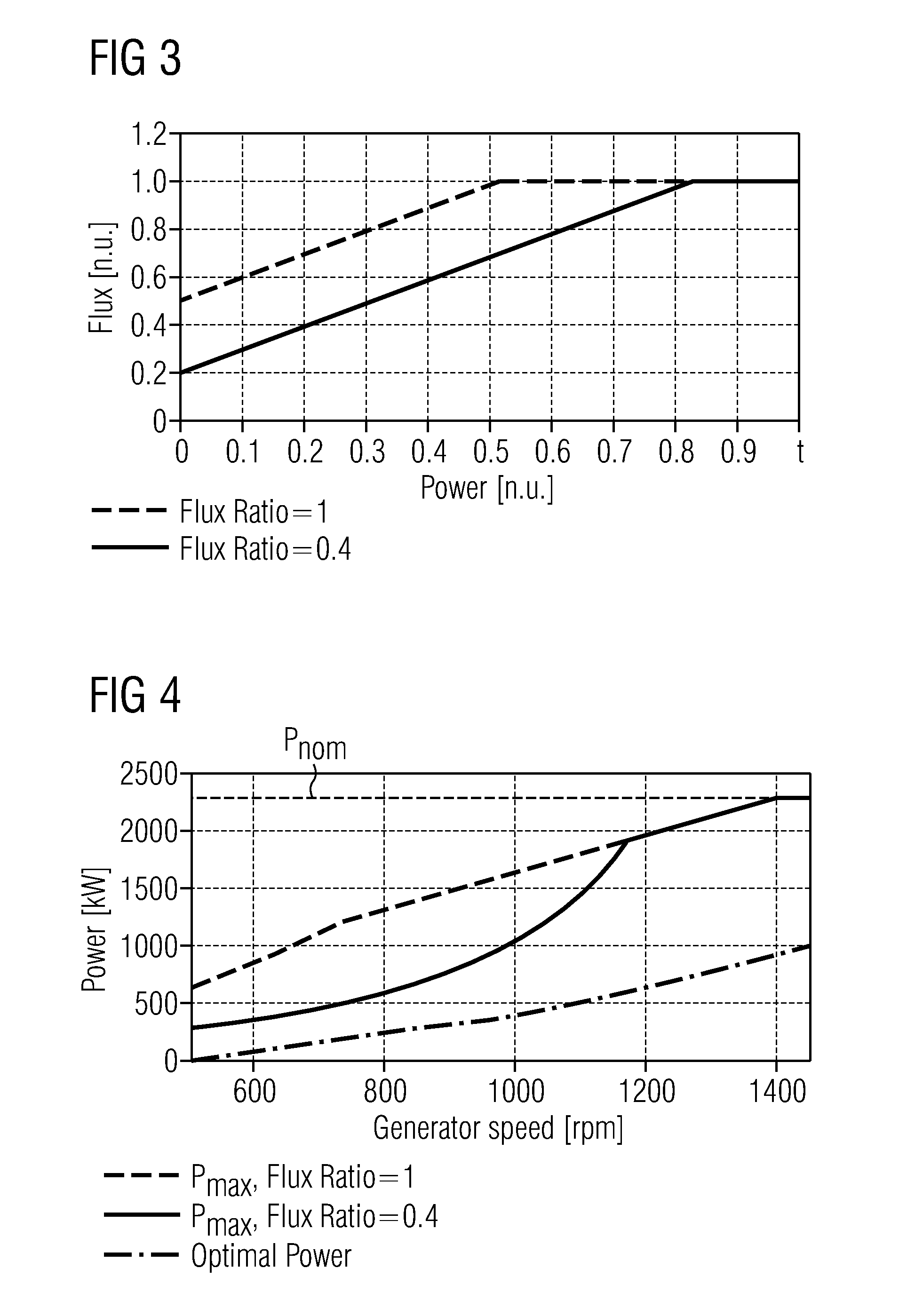
[0029]FIG. 3 shows a diagram representing the relationship between flux and output power provided by the embodiment of FIGS. 1 and 2, and

[0030]FIG. 4 shows the relationship between output power and generator speed as provided by the embodiment of FIGS. 1 and 2.

DETAILED DESCRIPTION OF INVENTION

[00...


PUM


Abstract

An asynchronous power generator for a wind turbine is provided. The asynchronous power generator includes a voltage supply and a stator with stator coils supplied with an alternating voltage by the voltage supply. The voltage supply is configured to adjust the voltage supplied to the stator coils based upon an output power generated by the wind turbine. Further, a method of voltage control is provided.

Description

CROSS REFERENCE TO RELATED APPLICATIONS[0001]This application is the US National Stage of International Application No. PCT / EP2009 / 060702 filed Aug. 19, 2009, and claims the benefit thereof. The International Application claims the benefits of European Patent Application No. 08016397.5 EP filed Sep. 17, 2008. All of the applications are incorporated by reference herein in their entirety.FIELD OF INVENTION[0002]This invention relates to an asynchronous power generator for a wind turbine, comprising a voltage supply and a stator with stator coils supplied with an alternating voltage by the voltage supply, and a method of voltage control therefore.BACKGROUND OF INVENTION[0003]Asynchronous generators of the state of the art typically comprise a rotor and a stator with stator coils. Oftentimes, the stator core is built using a laminate of thin metal sheets.[0004]In order to have the asynchronous generator to operate properly, the stator coils are supplied with an alternating voltage. Thi...

Claims


Application Information

Patent Timeline
IPC IPC(8): H02P9/04
CPCH02P9/007H02P2101/15H02P9/02
Inventor BIRKEMOSE, BOEGEDAL, PERGROENDAHL, ERIK
Owner SIEMENS GAMESA RENEWABLE ENERGY AS
Learn More