
Automated physical training system

Inactive Publication Date: 2006-06-20
P A INTERACTIVE
View PDF10 Cites 17 Cited by
  • Summary
  • Abstract
  • Description
  • Claims
  • Application Information

AI Technical Summary

Benefits of technology

[0031]The device of the present invention further measures reaction time. It is advantageous to begin movement toward an opposing player in the shortest amount of time possible after the auditory or visual stimulus indicating initiation of contact. Players with shorter reaction times potentially make contact with their opponents at higher velocities, thereby resulting in greater power outputs directed to the opponent.
[0032]Additionally, it is desirable to measure movement time. It is advantageous to cover greater distances in shorter periods of time before making contact with the opponent while blocking, charging, and tackling. Players with shorter movement times potentially make contact with an opponent at higher velocities resulting in greater power outputs. Deficiencies noted in movement time can be corrected through changes in the skill technique of the player and in practicing the skill.
[0033]The present invention is a system for automatically controlling and assessing a user athlete's physical training prowess at certain athletic skills. An apparatus of the present invention can be a treadmill sled having a frame, a rotatable continuous belt mounted on the frame, the belt presenting an upward directed support surface for supporting a user athlete, a training apparatus supported proximate the continuous belt and being operably coupled to the frame, and a performance measuring system. In one embodiment, the training apparatus can be in the form of a blocking dummy operably coupled to the frame with a dummy suppor

Problems solved by technology

The coaches' assessments on the playing field are not accurate due to changes in the environment, differences between observers, and the fact that these measurements are purely qualitative, while the quantitative measurements in the gymnasium are not accurate due to their non-specific nature, in that the movements are very different from the skills performed on the playing field.
As such, much of the efficiency and individualistic training focus is

Method used


Image

  • Automated physical training system
  • Automated physical training system
  • Automated physical training system

Examples


Example

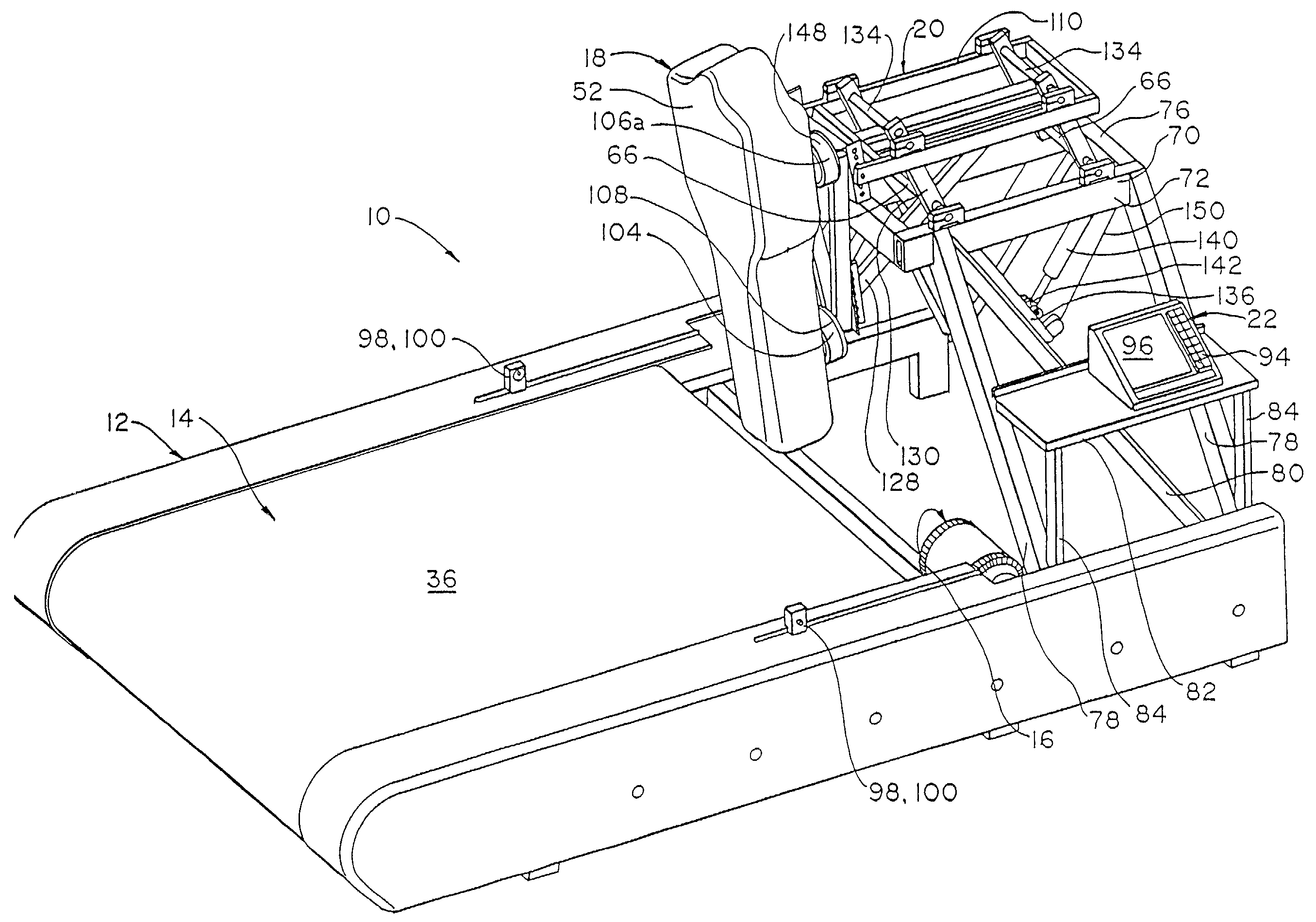
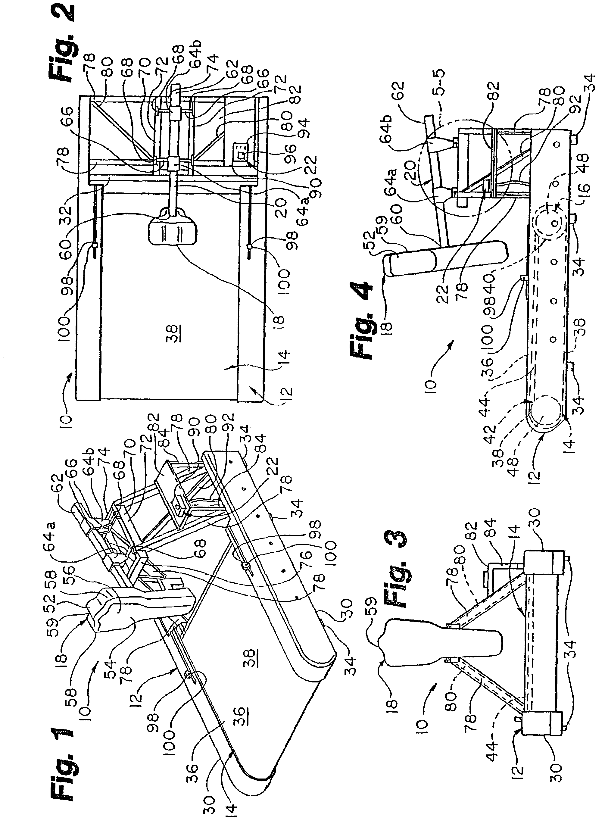
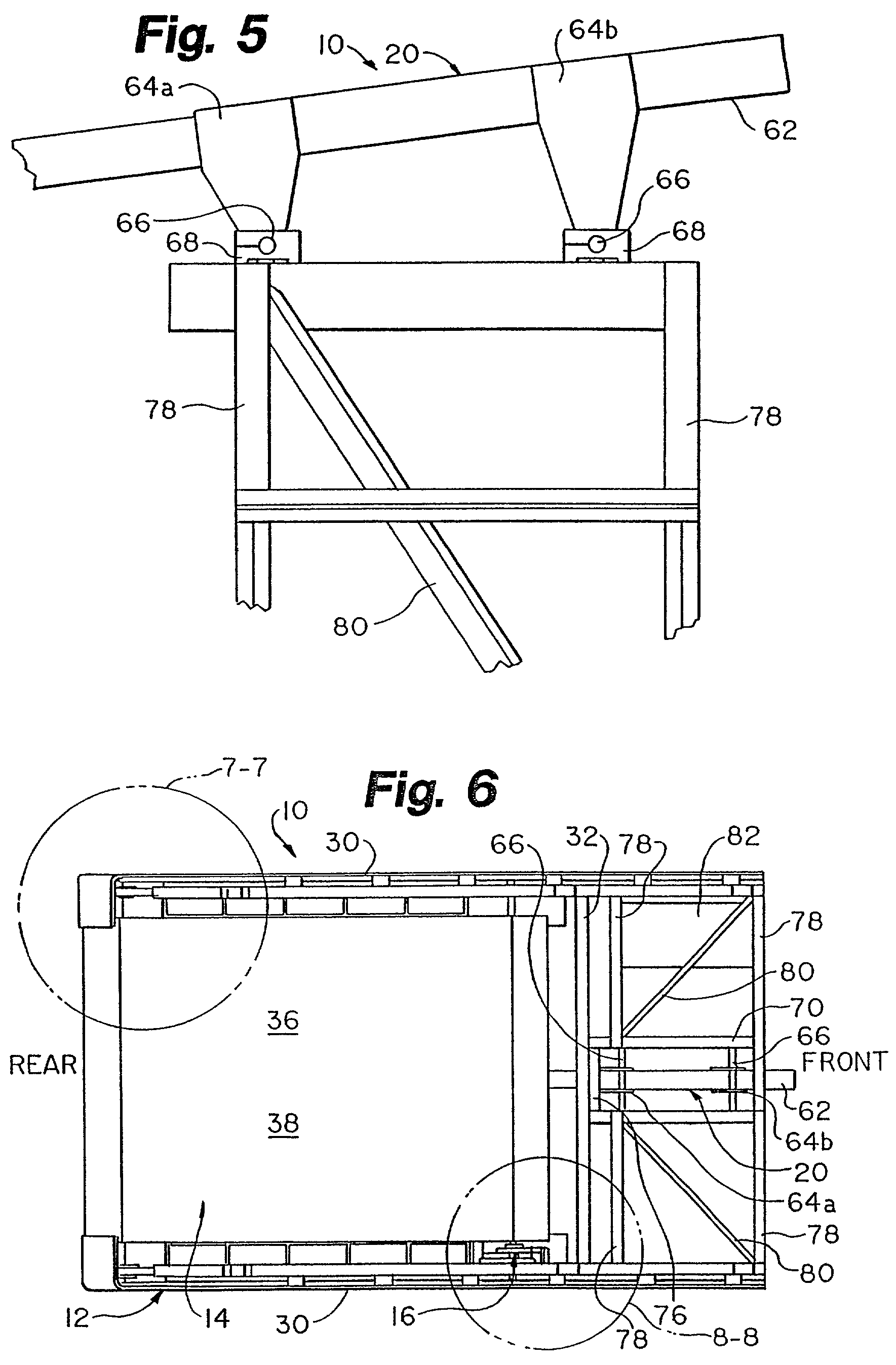
[0076]A first embodiment of the treadmill sled 10 is depicted in FIGS. 1–8. The frame 12 of the treadmill sled 10 has a pair of spaced apart, generally parallel side supports 30 that extend from the front to the rear of the treadmill sled 10. The side supports 30 are fixedly coupled together by a plurality of lateral supports 32 that extend between the two spaced apart sides supports 30 and are fixedly coupled thereto. A plurality of downward directed pads 34 are provided at the lower margin of the side supports 30 for engaging the surface on which the treadmill sled 10 is supported. The pads 34 are most useful when the treadmill sled 10 is disposed within a building and resting on a floor as distinct from being positioned on a practice field on a soil or other underlying surface.

[0077]The treadmill 14 of the treadmill sled 10 includes a continuous belt 36. The continuous belt 36 has an upward directed support surface 38 as depicted in FIGS. 1 and 2. The support surface 38 is direct...

Example

[0090]A second embodiment of the treadmill sled 10 of the present invention is depicted in FIG. 9. The treadmill sled 10 of FIG. 9 includes an enhanced controller 90 having a processor for calculating selected parameters based on sensed quantities. The braking system including the disk brake 48 and variable caliper 50 is used to estimate force production of a user athlete. A calibration procedure is generally conducted by the controller 90 to determine the force required to rotate the friction loaded disk brake 48. As a result of applying a regression equation, the pressure applied by the variable caliper 50 to the disk brake 48 is utilized to predict the force required to rotate the continuous belt 36 of the treadmill sled 10. After varying the pressure applied to the disk brake 48, a second experiment may be conducted to estimate the force required to turn the belt 36 of the treadmill sled 10. These values used in conjunction with the treadmill displacement as measured by the rota...

Example

[0091]A third embodiment of the treadmill sled 10 is depicted in FIGS. 10–14. A major difference between this embodiment of the treadmill sled 10 and the previous two embodiments of the treadmill sled 10 is found in the dummy support 20.

[0092]The dummy support 20 here includes a three point attachment 104 for supporting the blocking dummy 18. The three point attachment 104 includes two spaced apart shoulder attachments 106a, 106b and a lower torso attachment 108. The three point attachment 104 is fixedly coupled to a shiftable support frame 110.

[0093]The shiftable support frame 110 includes a subframe 112 for direct coupling to three point attachment 104. The subframe 112 has at least two flanges 114, the flanges 114 having a plurality of adjusting holes 116 defined therein. By selecting the desired adjusting hole 116 on the flanges 114, the relative height of the blocking dummy 118 can be adjusted as desired. The upper flange 114 is fixedly coupled to a horizontal support 120 by a ...


PUM


Abstract

The present invention is a system for automatically controlling and assessing a user athlete's physical training prowess at certain athletic skills. An apparatus of the present invention can be a treadmill sled having a frame, a rotatable continuous belt mounted on the frame, the belt presenting an upward directed support surface for supporting a user athlete, a training apparatus, and a performance measuring system. The training apparatus can include a blocking dummy and support frame, or a tether frame support system. Further, the performance measuring system can include programmable and automated control of the timing, duration, and scope/level of the physical training, and present quantitative assessment feedback to better maximize the applicable training regime, and to simplify the training sessions for supervisory personnel as well as the participating athlete(s).

Description

RELATED APPLICATIONS[0001]The present invention is a continuation-in-part of co-pending U.S. patent application Ser. No. 09 / 794,775, filed Feb. 27, 2001, now U.S. Pat. No. 6,575,879, which claims priority to U.S. Provisional Patent Application 60 / 193,316, filed Mar. 30, 2000; and this continuation-in-part claims priority to U.S. Provisional Patent Application 60 / 309,316, filed Aug. 1, 2001; each of the referenced Applications are incorporated herein by reference.TECHNICAL FIELD[0002]The present invention relates to a method and apparatus for assessing a user athlete. More particularly, the present invention relates to a physical training system employing automatic control, measurement, and assessment of at least one user athlete's performance.BACKGROUND OF THE INVENTIONFootball[0003]The skills that are important to a successful performance in the game of American football include blocking, charging, tackling, sprinting and pass blocking. Current methods of evaluating these skills in...

Claims


Application Information

Patent Timeline
IPC IPC(8): A63B22/00A63B21/015A63B22/02A63B24/00A63B69/34
CPCA63B22/02A63B69/345A63B21/015A63B2220/51A63B69/0053A63B69/34A63B22/025
Inventor HARNEY, RANDYFUCHS, RYAN
Owner P A INTERACTIVE
Learn More