Cup seal, and master cylinder in which it is used

a master cylinder and seal technology, applied in the direction of rotary clutches, fluid couplings, brake systems, etc., can solve the problems of limiting the supply of hydraulic fluid, difficult to form a liquid passage with a sufficiently large passage area, and difficult to elastically deform the base portion, so as to prevent the sticking of the base portion, prevent the effect of slipping and separating

Active Publication Date: 2011-09-01
BOSCH CORP
View PDF1 Cites 8 Cited by
  • Summary
  • Abstract
  • Description
  • Claims
  • Application Information

AI Technical Summary

Benefits of technology

[0014]According to the cup seal according to the invention configured in this way, as the base portion has an easy elastic deformation portion which elastically deforms in the axial direction comparatively easily, when causing the hydraulic fluid to flow from the back surface side of the base portion of the cup seal housed in the depressed portion, past the outer peripheral surface of the outer lip portion of the cup seal, to the front surface side of the cup seal, it is easily possible to cause the base portion to elastically deform in the axial direction due to a difference in pressure in front of and behind the cup seal.
[0015]Consequently, when causing the hydraulic fluid to flow from the back surface side of the cup seal to the front surface side in this way, the easy elastic deformation portion of the base portion elastically deforms, easily separating from a side wall of the depressed portion and, as well as it being possible to prevent a sticking of the base portion to the side wall, it is possible to reliably open a valve in a check valve function included in the cup seal. Then, as it is possible to prevent a sticking of the base portion to the side wall, it is possible to form a flow passage w

Problems solved by technology

When the base portion is stiff in this way, it is difficult for the base portion to elastically deform.
For this reason, no large gap being formed between the base portion of the cup seal and the housing depressed portion, it is difficult to form a liquid passage with a sufficiently large pa

Method used


Image

  • Cup seal, and master cylinder in which it is used
  • Cup seal, and master cylinder in which it is used
  • Cup seal, and master cylinder in which it is used

Examples


Embodiment Construction

[0024]Hereafter, using the drawings, a description will be given of a best mode for carrying out the invention.

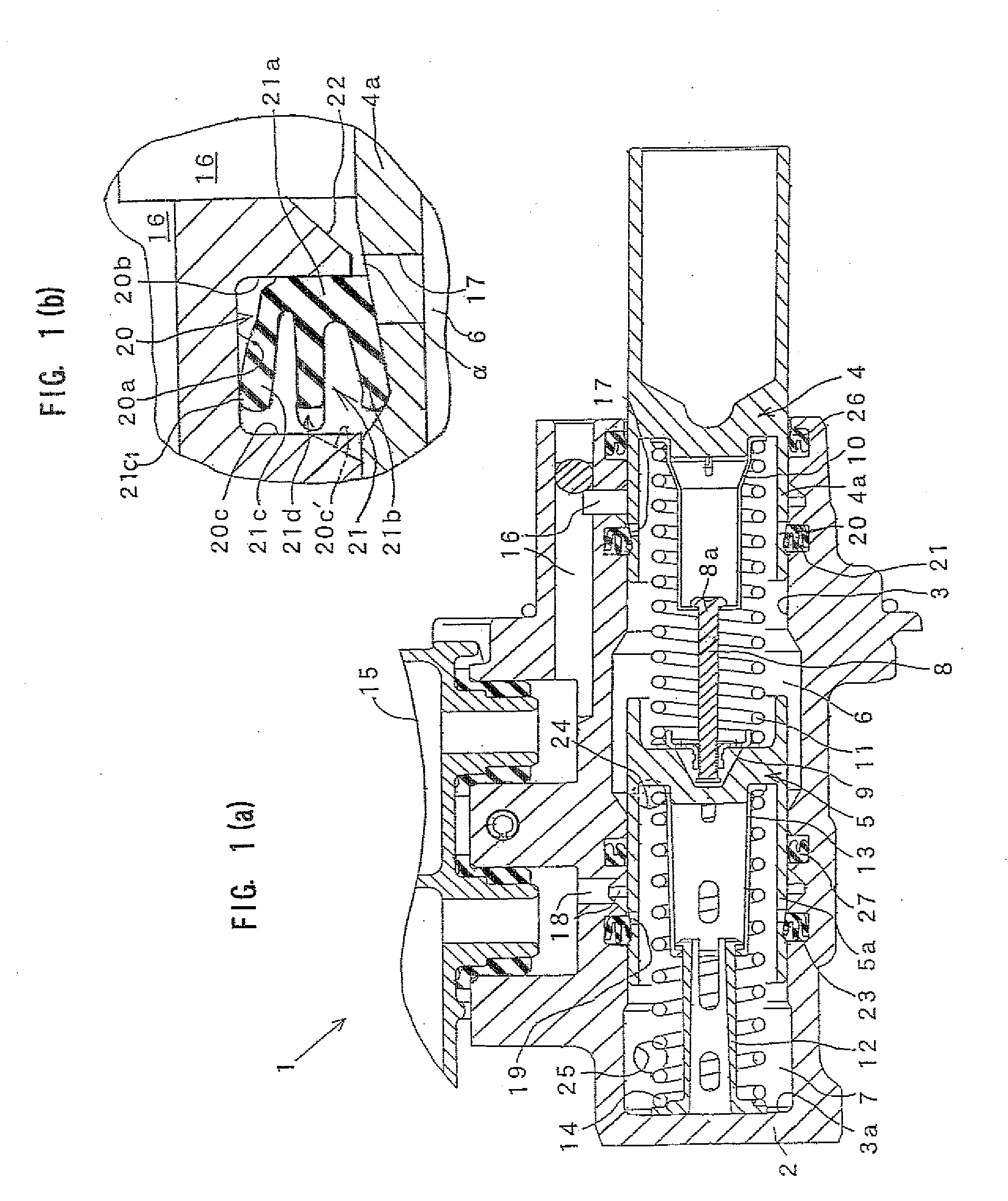
[0025]FIG. 1(a) is a vertical sectional view showing one example of an embodiment of a master cylinder including a cup seal according to the invention, FIG. 1(b) is a partial enlargement of a first cup seal portion in FIG. 1(a), and FIGS. 2(a) and (b) are diagrams showing the cup seal used in the master cylinder. The “front” and “rear” of the master cylinder in the following description refer respectively to “left” and “right” in the drawings.

[0026]As shown in FIG. 1(a), a plunger type master cylinder 1, being used as a master cylinder of a brake system, includes a cylinder main body 2. A cylinder hole 3 is formed inside the cylinder main body 2.

[0027]A primary piston 4 and secondary piston 5 are slidably inserted into the cylinder hole 3. The primary piston 4 is configured so that it moves to the left due to an unshown brake pedal, or brake booster which boosts and outputs...


PUM


Abstract

A cup seal (21) of the invention includes an intermediate lip portion (21d), positioned between an inner lip portion (21b) and an outer lip portion (21c), provided in a base portion (21a). The intermediate lip portion (21d) is configured in such a way that first intermediate lip portions (21d1), communication passages (21d3), second intermediate lip portions (21d2), whose axial direction length is less than that of the first intermediate lip portions (21d1), and the communication passages (21d3), which have no lip portion, are cyclically disposed, in this order, in the peripheral direction. An easy elastic deformation portion of the base portion (21a) which elastically deforms easily is formed by the second intermediate lip portions (21d2) and communication passages (21d3) and, by the easy elastic deformation portion elastically deforming easily when supplying liquid, a flow passage with a larger passage area is formed.

Description

BACKGROUND ART[0001]The present invention relates to a technical field of a cup seal, and a plunger type master cylinder including the cup seal, used in a cylinder device configured of a cylinder, such as a master cylinder of a brake or clutch in a vehicle such as an automobile, and a sliding member disposed in such a way that it can move inside the cylinder relative to the axial direction thereof.[0002]To date, in a hydraulic brake system or hydraulic clutch system of an automobile, a master cylinder which generates hydraulic pressure in accordance with a tread force of a brake pedal or clutch pedal has been used to operate a brake or clutch. As the master cylinder, a plunger type master cylinder including a cylinder main body which has a cylinder hole, a piston, slidably inserted into the cylinder hole, which demarcates a hydraulic chamber, a communication passage, provided in the cylinder main body, which communicates with a reservoir, a relief port, formed in the piston, which c...

Claims


Application Information

Patent Timeline
IPC IPC(8): B60T11/26F16J15/32B60T11/16B60T11/228
CPCF16J15/3236B60T11/236
Inventor AOKI, TOMOHIROSHIWA, MASAKI
Owner BOSCH CORP
Why Eureka
Try Eureka