Drive device for alternating current motor and electric motor vehicle
a technology of alternating current motor and electric motor, which is applied in the direction of electronic commutators, dynamo-electric converter control, dynamo-electric gear control, etc., can solve the problems of increasing the amount of attachment and adjustment work, increasing the cost, and the like due to the essential information sensor, so as to reduce the generation the effect of minimizing the harmonic wave generation amount and reducing the amount of electromagnetic noise and loss
- Summary
- Abstract
- Description
- Claims
- Application Information
AI Technical Summary
Benefits of technology
Problems solved by technology
Method used
Image
Examples
embodiment 1
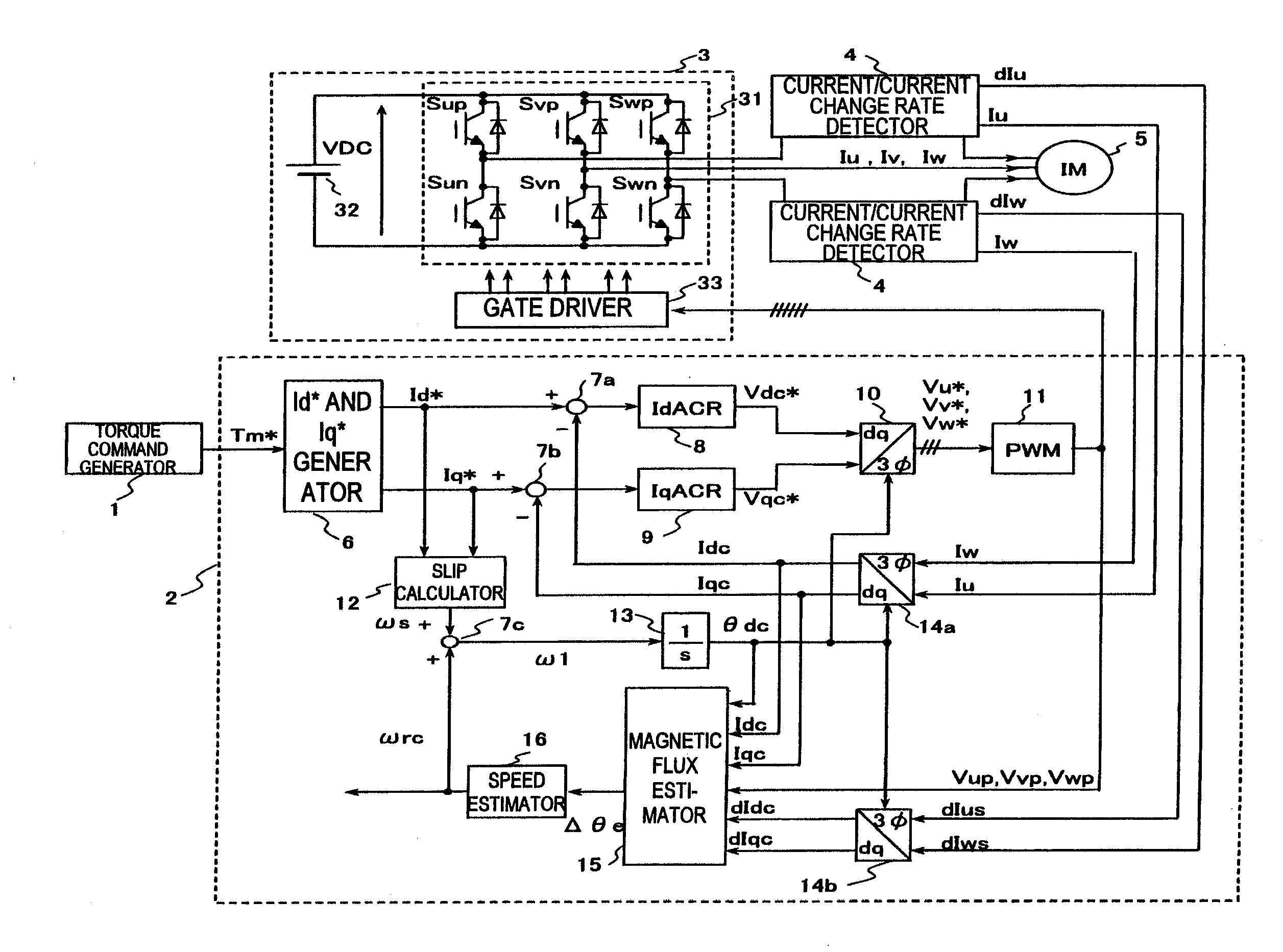
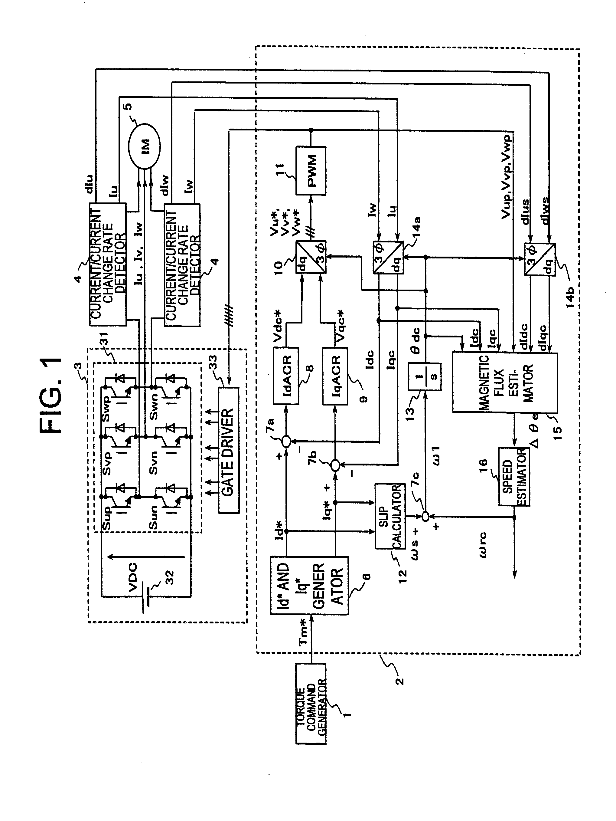
[0064]FIG. 1 is a block diagram illustrating a configuration of a drive device for an alternating current motor according to Embodiment 1 of the present invention.
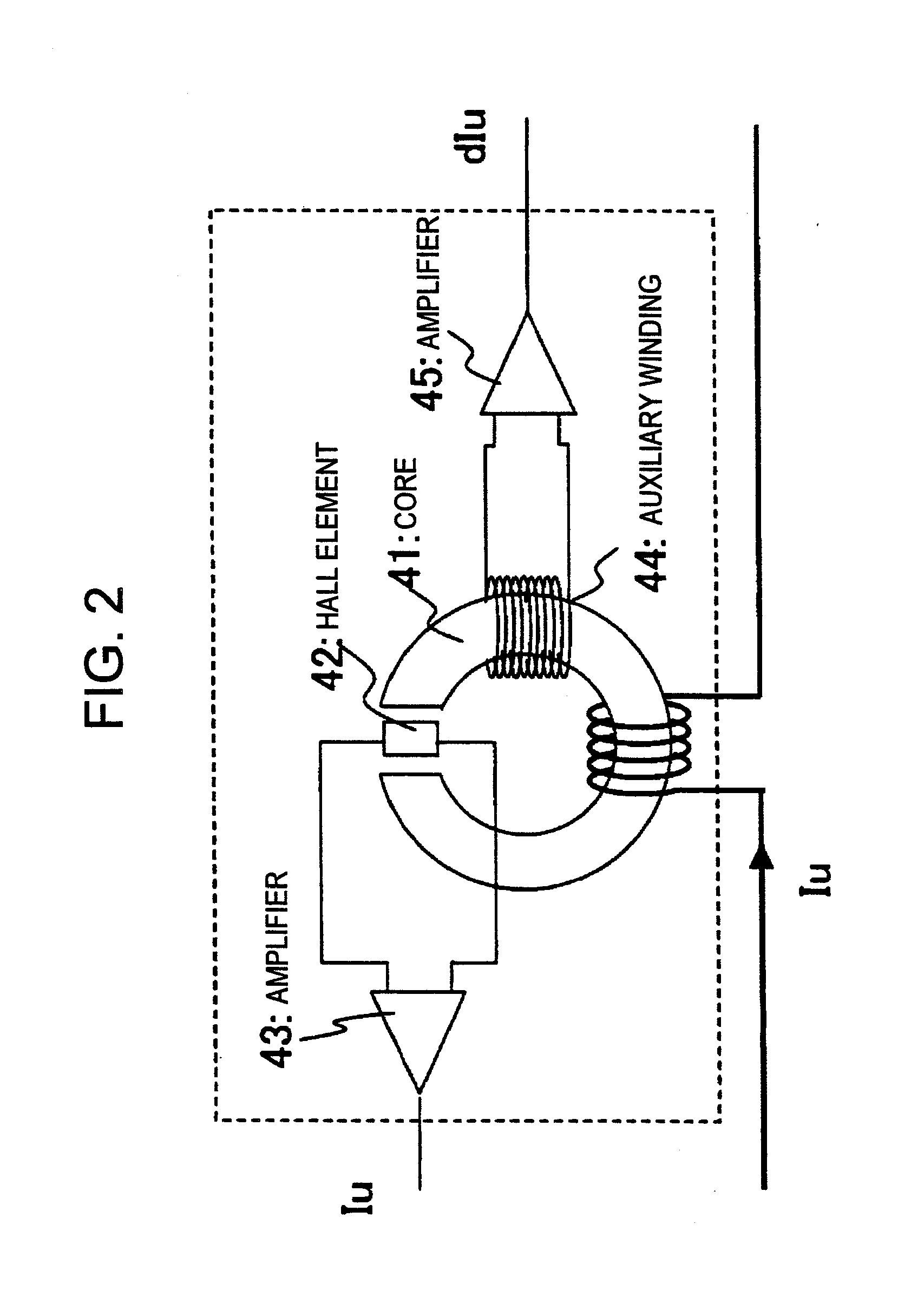
[0065]This device is intended to drive a three-phase induction motor. In the rough definition, this device includes: a torque command generator 1; a controller 2; an inverter 3 including an inverter main circuit 31, an inverter power supply 32, and a gate driver 33; a current / current change rate detector 4; and a three-phase induction motor 5 (hereinafter, abbreviated as induction motor) to be driven.
[0066]The torque command generator 1 is means for issuing a generation torque command Tm* of the induction motor 5, and is a controller disposed upstream of the controller 2. A speed controller which adjusts the number of revolutions of the induction motor 5 may be provided further upstream of the torque command generator, but is omitted in the present embodiment.
[0067]The controller 2 calculates a voltage applied to the induc...
embodiment 2
[0085]Next, Embodiment 2 of the present invention is described.
[0086]In Embodiment 1, a description is given on the assumption that the controller 2 is realized by the analog circuit, and hence high-speed processing is essential to realize the controller by digital control. As a matter of course, if special gate logic is employed, it is not impossible to realize the controller by digitalization, but a circuit scale will be enormous.
[0087]In Embodiment 2, on the assumption of applying a microcomputer for industrial purposes or the like, a practical example is described with reference to FIG. 6 to FIG. 10.
[0088]FIG. 6 is a block configuration diagram illustrating a controller 2B which is a characteristic feature of Embodiment 2. Embodiment 2 is implemented by adopting the controller 2B instead of the controller 2 in FIG. 1.
[0089]In FIG. 6, the blocks denoted by part numbers 6 to 14 and 16 are identical with those denoted by the same numbers illustrated in FIG. 1. The characteristic fe...
embodiment 3
[0099]Next, Embodiment 3 of the present invention is described.
[0100]In Embodiments 1 and 2, the control target is the induction motor, and in Embodiment 3, a permanent magnet synchronous motor (hereinafter, abbreviated as PM motor) is applied. The PM motor can realize downsizing and higher efficiency compared with the induction motor, and hence application purposes thereof are expected to be expanded hereafter.
[0101]FIG. 11 is a configuration diagram according to Embodiment 3, which is illustrated on the basis of Embodiment 2 (FIG. 6). A controller 2C is substantially the same as the controller 2B in FIG. 6, and no change is made thereon except the slip calculator 12 is removed. In addition, the electric motor is replaced with a PM motor 5C.
[0102]In the PM motor, the drive frequency ω1 and the frequency ωrc of the number of revolutions are always synchronized with each other, and hence the slip frequency does not need to be added, so that the control configuration is more simplifie...
PUM
 Abstract
Description
Claims
Application Information
 - R&D
- Intellectual Property
- Life Sciences
- Materials
- Tech Scout
- Unparalleled Data Quality
- Higher Quality Content
- 60% Fewer Hallucinations
Browse by: Latest US Patents, China's latest patents, Technical Efficacy Thesaurus, Application Domain, Technology Topic, Popular Technical Reports.
© 2025 PatSnap. All rights reserved.Legal|Privacy policy|Modern Slavery Act Transparency Statement|Sitemap|About US| Contact US: help@patsnap.com


