
Power supply system, powered device, and power reception method

a power supply system and power reception technology, applied in the field of power supply systems, powered devices, and power reception methods, can solve problems such as detection failures and unbalanced transmission lines

Inactive Publication Date: 2011-08-18
CANON KK
View PDF14 Cites 16 Cited by
  • Summary
  • Abstract
  • Description
  • Claims
  • Application Information

AI Technical Summary

Benefits of technology

[0013]It is desirable to provide a power supply system and a powered device that can correct impedance unbalance in a transmission line before power supply is started, without the need to replace an already-existing power supply unit and other equipment.
[0015]According to the present invention, a system having enhanced connectivity can be established in which a powered device corrects an impedance unbalance in a transmission line. Further, connectivity between power sourcing equipment and a powered device can be enhanced.

Problems solved by technology

When the relationship the stray capacitance C1≠ the stray capacitance C2 is satisfied, the transmission line becomes unbalanced.
As the amplitude of the superimposed AC noise increases, a value of the current generated as a result of the PD's reception of the detection voltage exceeds a current value range in which a detection device in the PSE can detect the PD, so that detection failure may occur.

Method used


Image

  • Power supply system, powered device, and power reception method
  • Power supply system, powered device, and power reception method
  • Power supply system, powered device, and power reception method

Examples


Embodiment Construction

[0025]Various exemplary embodiments, features, and aspects of the invention will be described in detail below with reference to the drawings.

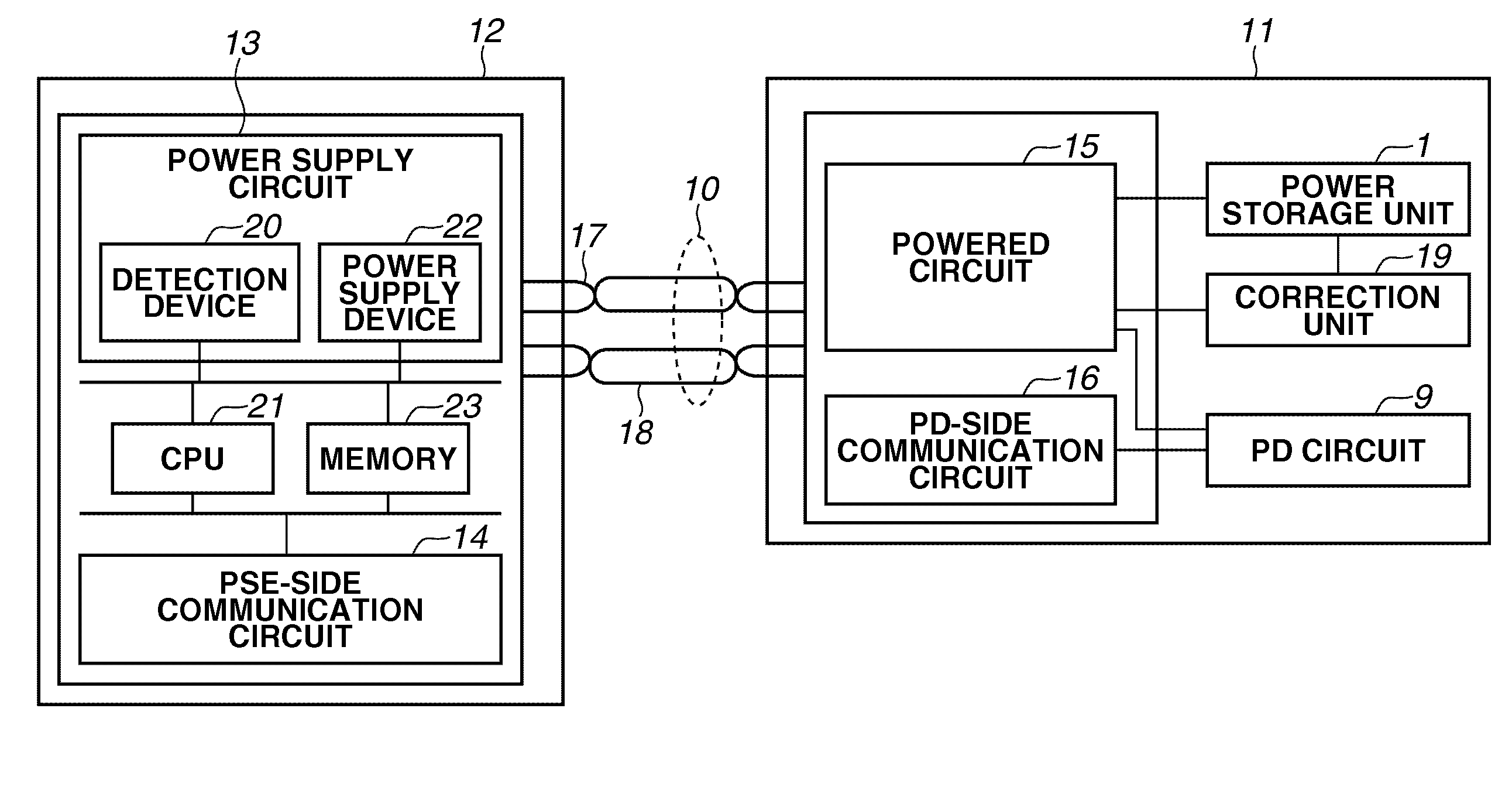
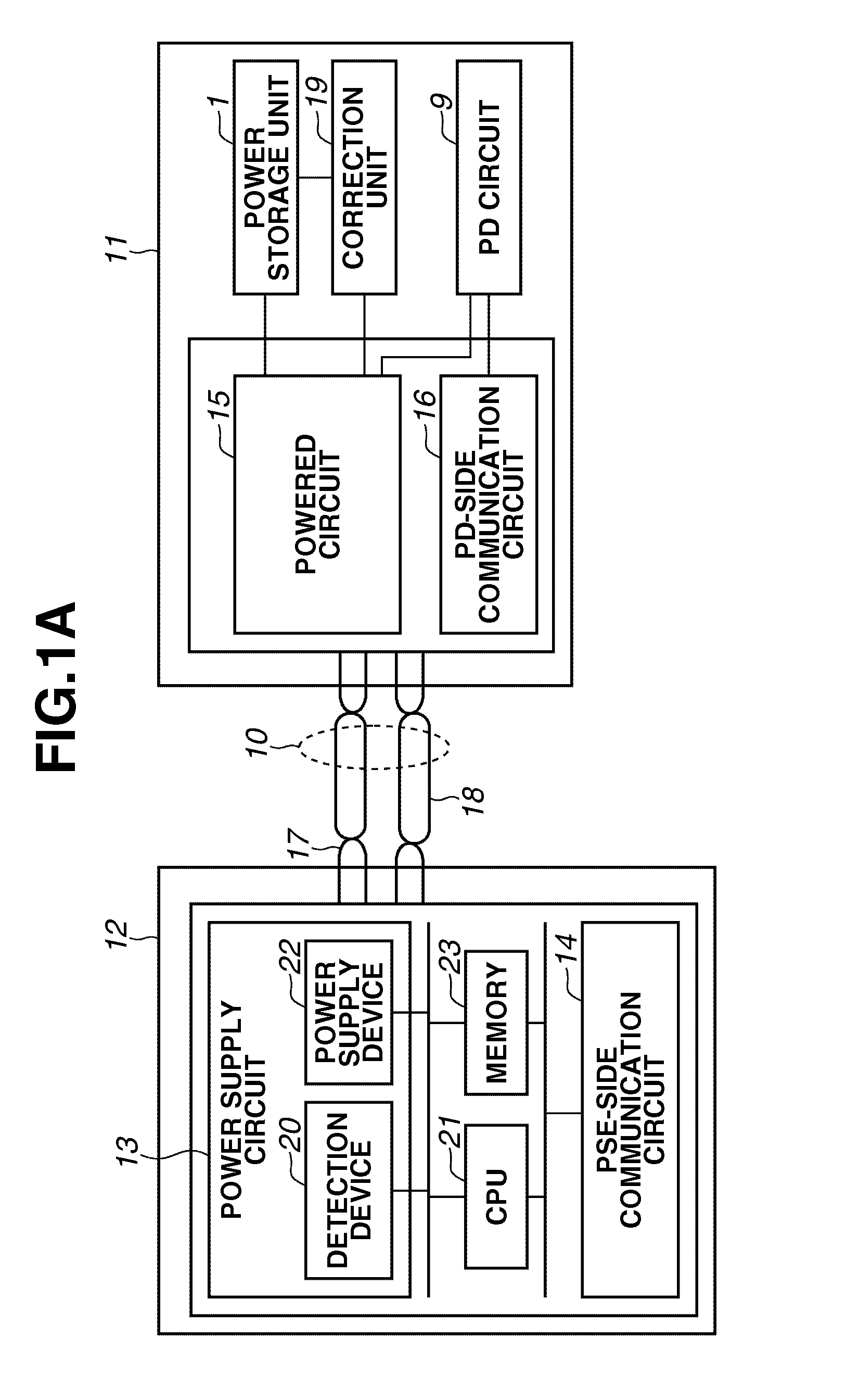
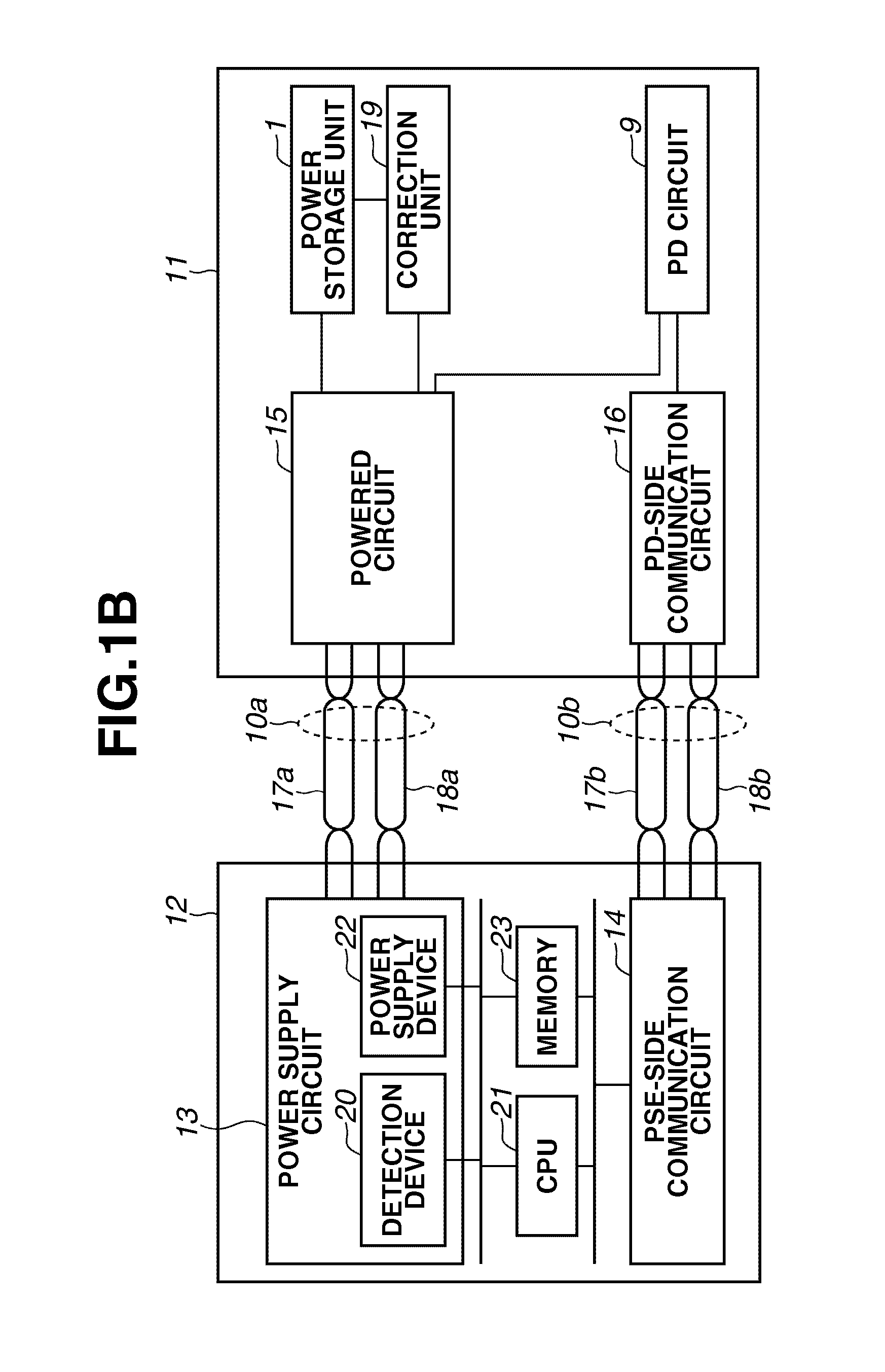
[0026]FIGS. 1A and 1B illustrate configurations of a power supply system according to a first exemplary embodiment of the present invention.

[0027]With reference to FIG. 1A, the configuration of the power supply system according to the first exemplary embodiment of the present invention will be described. Power sourcing equipment 12 and a powered device 11 are connected to each other via a transmission line 10. In this example the transmission line 10 includes a pair of constituent lines 17 and 18.

[0028]In the present exemplary embodiment, the lines 17 and 18 each are a twisted-pair cable, and provide balanced transmission. In the present exemplary embodiment, although twisted-pair cables are employed, the lines 17 and 18 need not necessarily be composed of twisted-pair cables. Each of the lines 17 and 18 may be a single line.

[0029]A power suppl...


PUM


Abstract

Power sourcing equipment starts power supply after outputting a detection signal to a transmission line and detecting that a powered device is connected with the transmission line. The powered device includes a power storage unit configured to store power obtained from the detection signal output from the power sourcing equipment, and a correction unit configured to correct an impedance unbalance in the transmission line. The power storage unit provides the stored power to the correction unit.

Description

BACKGROUND OF THE INVENTION[0001]1. Field of the Invention[0002]The present invention relates to a power supply system, a powered device, and a power reception method for correcting an impedance unbalance in a transmission line used to supply power.[0003]2. Description of the Related Art[0004]The Power over Ethernet (PoE, registered trademark) system specified by the Institute of Electrical and Electronic Engineers (IEEE) 802.3af standard is conventionally known as a system for supplying power via a communication line, such as an Ethernet (registered trademark) cable.[0005]In PoE, power sourcing equipment (PSE) supplies power to a powered device (PD). The IEEE 802.3af standard specifies a sequence for such power supply. In PoE, the PSE supplies power to the PD through three phases, detection, classification, and power supply. The PD incorporates a signature resistance of 25 KΩ (representative value). In the detection phase, the PSE outputs a low voltage to detect the connection of t...

Claims


Application Information

Patent Timeline
Patent Type & Authority Applications(United States)
IPC IPC(8): G06F11/30
CPCH04L12/10H04L25/0278H04L25/0274H04L25/02H04L25/12
Inventor MIZUTANI, KOICHI
Owner CANON KK
Learn More