
System and method for fabricating a dental healing abutment

Inactive Publication Date: 2011-08-18
PROCEREX DENTAL LAB
View PDF31 Cites 31 Cited by
  • Summary
  • Abstract
  • Description
  • Claims
  • Application Information

AI Technical Summary

Benefits of technology

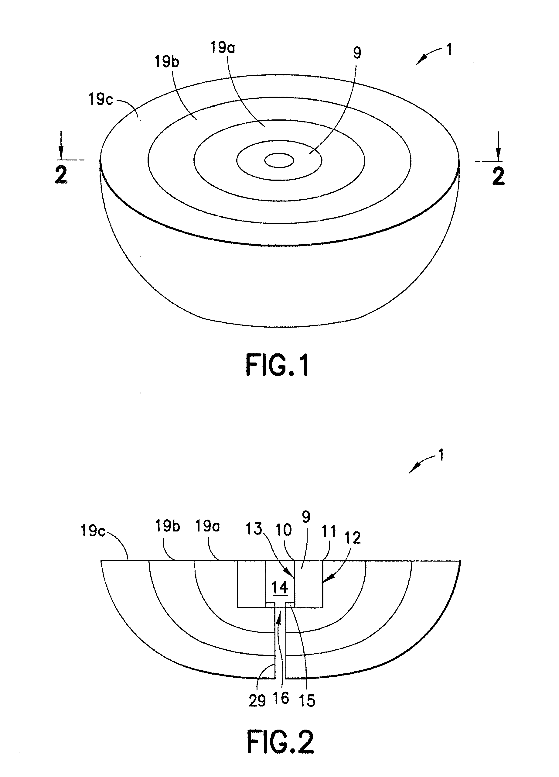
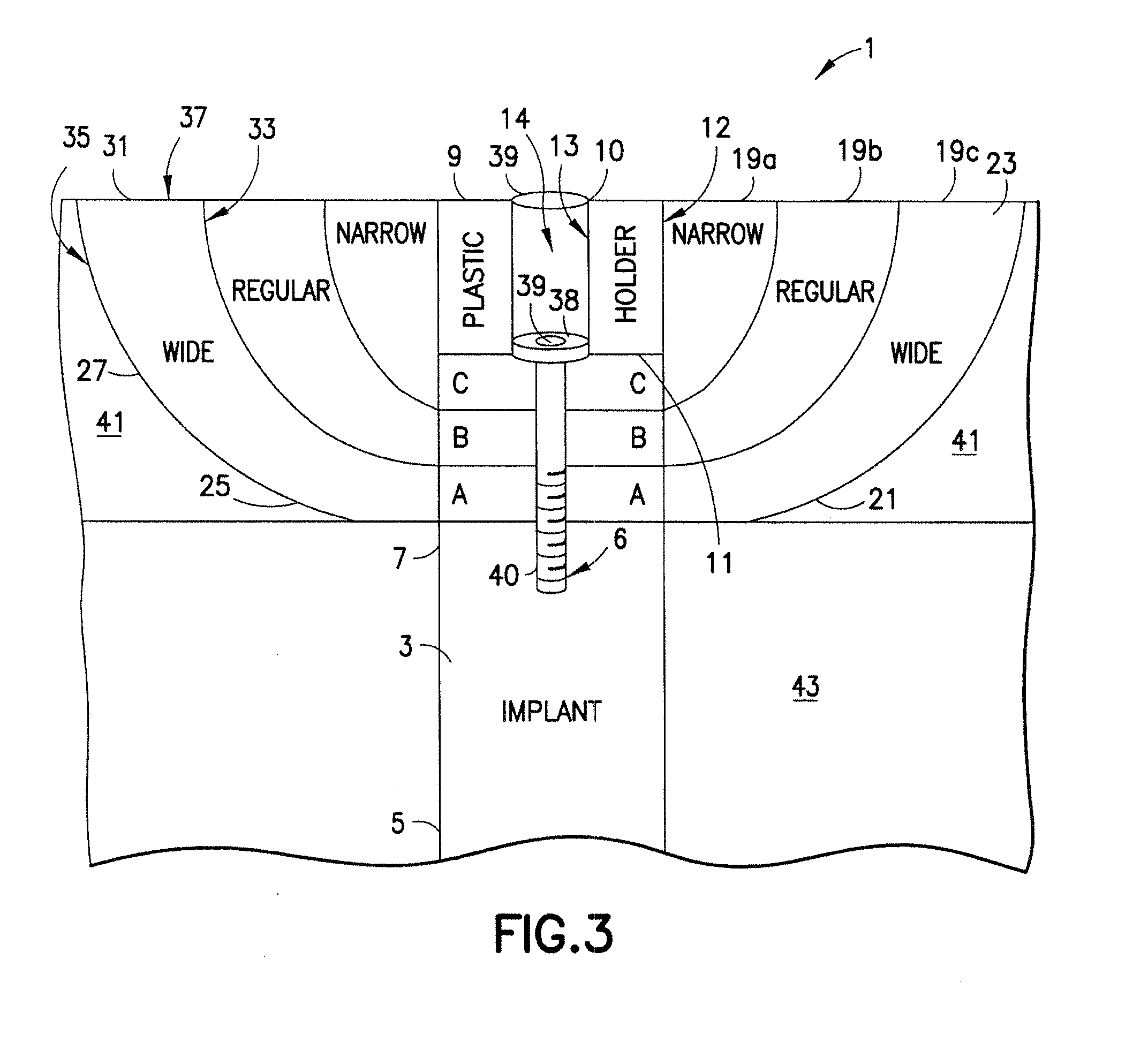
[0012]Each nestable shell may be separated from the other nestable shell to adjust the diameter of the healing abutment assembly, allowing a dentist to fit the healing abutment assembly between the surrounding teeth. When the preferred number of nestable shells have been removed, an incision is made in the gingival tissue to expose the second end of the implant. The cap or other closing means is removed from the implant and the screw of the healing abutment assembly is engaged with the hollow opening of the implant, thereby tightly securing the healing abutment assembly in place. The healing abutment assembly remains secured in the implant until the gingival tissue can grow around the healing abutment assembly. In the secured position, a top side of the healing abutment assembly, defined by the distal ends of each side wall and the holder, is covered by gingival tissue.
[0014]In another embodiment, a healing abutment for use with a dental implant includes a generally hemispherical, unitary member having a planar top surface and a hollow portion traversing the generally hemispherical, unitary member in a longitudinal direction from the top surface toward a bottom surface opposite the top surface, an inwardly facing flange extending from an inner surface of the hollow portion at a position in proximity to the bottom surface to define an opening that is cross sectionally smaller than the hollow portion; and at least one circumferential groove etched about the hollow portion on the top surface of the generally hemispherical, unitary member facilitating removal of at least one layer of the generally hemispherical, unitary member to achieve a desired dimension of the healing abutment.

Problems solved by technology

However, the prior art does not disclose healing abutments that are adjustable in terms of size and emergence profile.
The inventory management of abutments of different shapes and sizes is costly and complicated.

Method used


Image

  • System and method for fabricating a dental healing abutment
  • System and method for fabricating a dental healing abutment
  • System and method for fabricating a dental healing abutment

Examples


Embodiment Construction

[0026]All examples and conditional language recited herein are intended for teaching purposes to aid the reader in understanding the principles of the disclosure and the concepts contributed by the inventor to furthering the art, and are to be construed as being without limitation to such specifically recited examples and conditions.

[0027]Moreover, all statements herein reciting principles, aspects and embodiments of the disclosure, as well as specific examples thereof, are intended to encompass both structural and functional equivalents thereof. Additionally, it is intended that such equivalents include both currently known equivalents as well as equivalents developed in the future, i.e., any elements developed that perform the same function, regardless of structure.

[0028]With reference to the drawings, embodiments of the present disclosure will be described. As shown in FIGS. 1-3, a healing abutment assembly 1 is shown having: a holder 9, a plurality of nestable shells 19 and a mo...


PUM


Abstract

A dental healing abutment assembly having a tubular holder and a plurality of removable nestable shells. Each nestable shell has a proximal end and a distal end open to permit the nesting of the shell with the holder or other nestable shells. The proximal end of each nestable shell is defined by a base plate. The tubular holder and the nestable shells each have a pass through hole for accommodating a mounting member. The healing abutment assembly is attached to a dental implant impacted in a patient's jawbone by way of the mounting member. Furthermore, a system and method are provided for fabricating a permanent abutment by decoding an identifier disposed on the healing abutment.

Description

PRIORITY[0001]This application is a continuation-in-part of U.S. patent application Ser. No. 12 / 707,244 filed Feb. 17, 2010 entitled “Dental Healing Abutment”, the contents of which are hereby incorporated by reference in the entirety.[0002]This application also claims priority to U.S. Provisional Application No. 61 / 307,107 filed Feb. 23, 2010 entitled “System and Method for Fabricating a Dental Healing Abutment”, the contents of which are hereby incorporated by reference in the entirety.FIELD[0003]The present disclosure relates generally to the field of dental implants and in particular to a healing abutment customizable in emergence profile and size.DESCRIPTION OF THE PRIOR ART[0004]Single tooth dental implant systems are well known in the prior art. An important system for replacing a single tooth is comprised of several parts, namely, an implant, at least one abutment, and a prosthesis. First, the implant is placed into the jawbone. The implant is generally a threaded metal memb...

Claims


Application Information

Patent Timeline
IPC IPC(8): A61C8/00
CPCA61C8/008
Inventor LAIZURE, JR., ROBERT S.
Owner PROCEREX DENTAL LAB
Learn More