
Reinforced plate glass and method for manufacturing the same

a technology of reinforced plate glass and reinforced glass, which is applied in glass tempering apparatus, manufacturing tools, transportation and packaging, etc., can solve the problems that the above-mentioned chemical strengthening cannot be realized, and achieve the effects of reducing the cost of work equipment, reducing the degree of freedom of work, and simplifying the use of work equipmen

Inactive Publication Date: 2011-08-18
NIPPON ELECTRIC GLASS CO LTD
View PDF37 Cites 64 Cited by
  • Summary
  • Abstract
  • Description
  • Claims
  • Application Information

AI Technical Summary

Benefits of technology

[0033]As described above, according to the present invention, already formed plate glasses are used as the core plate glass and the surface-layer plate glasses, and those plate glasses are melt-bonded to each other by performing heat treatment to the core plate glass and the surface-layer plate glass under the state in which the core plate glass and the surface-layer plate glass are laminated together. Thus, work for melt-bonding the core plate glass and the surface-layer plate glass is eliminated in the execution of a process of forming a plate glass in which molten glass is formed into a sheet shape. As a result, the situation where the melt-bonding work is strictly restricted is avoided, and the degree of freedom in the work becomes larger. In addition, the simplification of work equipment, the reduction of the cost of the work equipment, and the reduction of production cost are attained, and moreover, the improvement of workability and productivity is attained. Besides, even in the case where the kind of a reinforced plate glass to be produced is changed, large-scale changes of equipment and work are not required, and it is possible to easily and promptly cope with the change of the kind of the reinforced plate glass.

Problems solved by technology

However, there is a problem in that if alkali-free glass is used for satisfying the demands as mentioned above, the above-mentioned chemical strengthening cannot be realized.

Method used


Image

  • Reinforced plate glass and method for manufacturing the same
  • Reinforced plate glass and method for manufacturing the same
  • Reinforced plate glass and method for manufacturing the same

Examples


Embodiment Construction

[0040]Hereinafter, embodiments of the present invention are described based on the accompanying drawings.

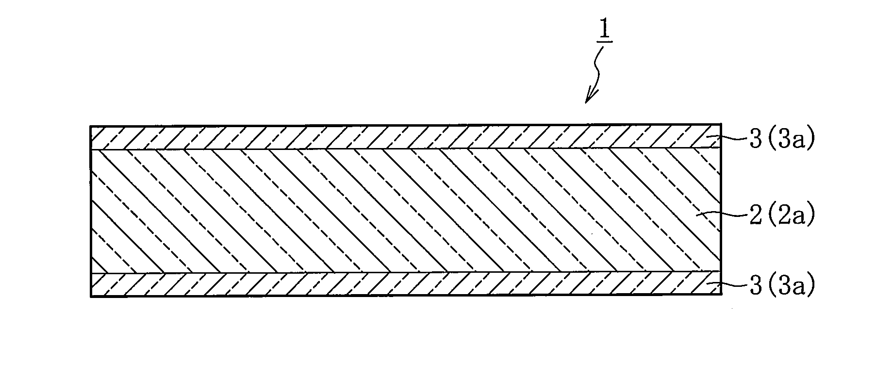
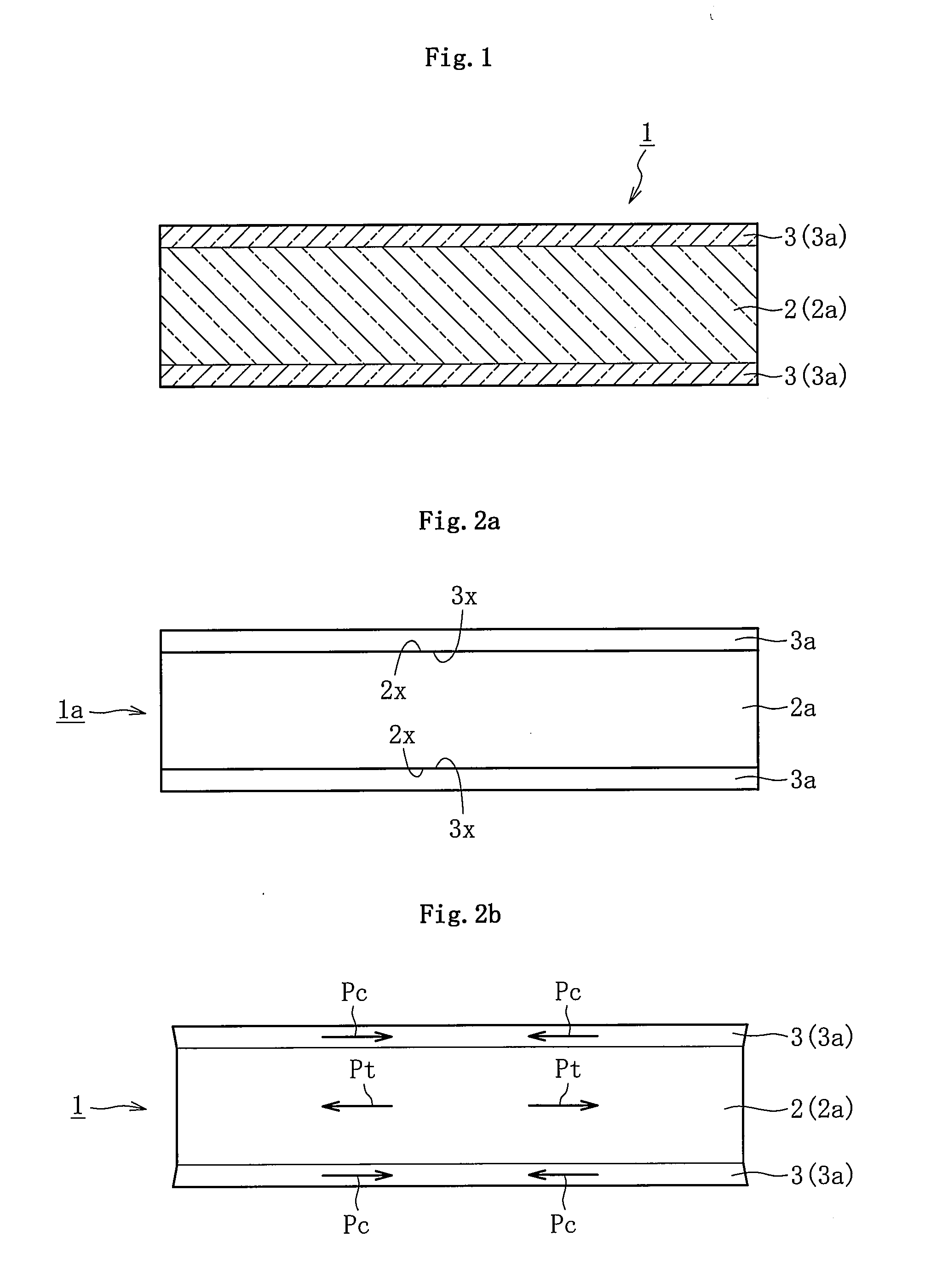
[0041]FIG. 1 illustrates a reinforced plate glass 1 according to an embodiment of the present invention. The reinforced plate glass 1 is, for example, a reinforced plate glass to be mounted on an electronic device such as a touch panel, a display, or a solar cell, the reinforced plate glass being required particularly for outdoor installation.

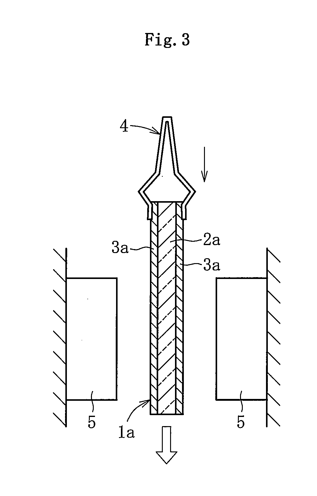
[0042]As illustrated in the figure, the reinforced plate glass 1 is a glass laminate which has a three-layer structure formed of a core portion 2 corresponding to a core plate glass 2a and surface layer portions 3 corresponding to surface-layer plate glasses 3a each arranged on one of both surface sides of the core plate glass 2a in its thickness direction. That is, the reinforced plate glass 1 is one obtained by closely fixing one core plate glass 2a forming the core portion 2 and two surface-layer plate glasses 3a forming the surface layer...


PUM

PropertyMeasurementUnit
Temperatureaaaaaaaaaa
Thicknessaaaaaaaaaa
Widthaaaaaaaaaa

Abstract

Provided is a method, including: performing heat treatment, under a state in which a thick core plate glass (2a) having a higher thermal expansion coefficient and a thin surface-layer plate glass (3a) having a lower thermal expansion coefficient are laminated together, so that the laminated portion has a temperature equal to or higher than the lower softening point out of the softening points of the core plate glass (2a) and the surface-layer plate glass (3a), thereby melt-bonding the core plate glass (2a) and the surface-layer plate glass (3a); and then performing cooling so as to attain a temperature less than the lower strain point out of strain points of the core plate glass (2a) and the surface-layer plate glass (3a), to thereby form a compression stress in a surface layer portion (3) corresponding to the surface-layer plate glass (3a) and form a tensile stress in a core portion (2) corresponding to the core plate glass (2a).

Description

TECHNICAL FIELD[0001]The present invention relates to a reinforced plate glass used for a substrate material, a cover glass member, or the like to be mounted on, for example, an image display portion or an image input portion of various kinds of portable information terminals typified by a mobile phone and a PDA and an electronic appliance typified by a liquid crystal display, or on a solar light inlet of a solar cell, and to a method for manufacturing the same.BACKGROUND ART[0002]As is known well, progress has been continuously made in recent years in technological innovation regarding various kinds of information-related terminals, for example, portable appliances such as a mobile phone, a digital camera, and a PDA or an image display apparatus such as a liquid crystal television. Such information-related terminals include a transparent substrate mounted thereon, as a substrate material for displaying information such as images and characters or for inputting information with a to...

Claims


Application Information

Patent Timeline
IPC IPC(8): B32B17/00C03B23/203B32B7/02C03B23/037
CPCC03B23/037Y10T428/2495C03B23/203Y02P40/57
Inventor TOMAMOTO, MASAHIROTAKAYA, TATSUYATAKIMOTO, HIROSHI
Owner NIPPON ELECTRIC GLASS CO LTD
Learn More