
System and method for changing spectral range of a cryogenically cooled detector

a detector and cryogenically cooled technology, applied in the field of infrared cryogenically cooled detectors, can solve the problems of noisy noise and degradation of images, the inability to employ moving parts within the vacuum,

Active Publication Date: 2011-08-18
RAFAEL ADVANCED DEFENSE SYSTEMS
View PDF37 Cites 11 Cited by
  • Summary
  • Abstract
  • Description
  • Claims
  • Application Information

AI Technical Summary

Benefits of technology

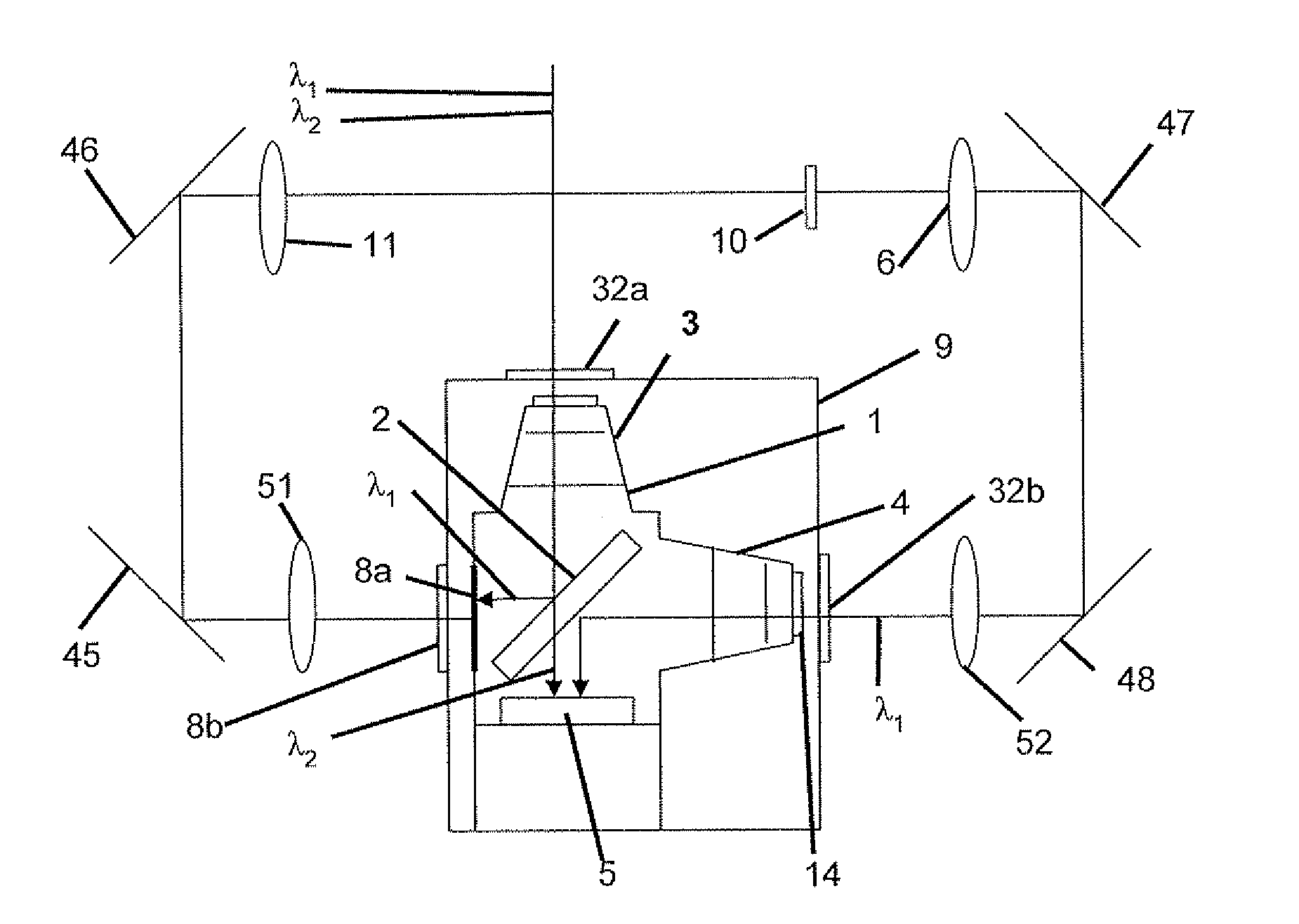
[0014]In some embodiments, a dichroic mirror is disposed inside the cold shield in front of an infra-red detector. The dichroic mirror has a high reflectance at a first spectral range and a high transmittance at a second spectral range. The detecting device includes a first arm and a second arm of the cold shield to accommodate respective optical channels for the first spectral range and for the second spectral range. Preferably, a removable selective mirror having a high reflectance at the first spectral range is disposed outside the cold shield. Most preferably, the removable selective mirror prevents reception by the detecting device of incoming radiation at the second spectral range.
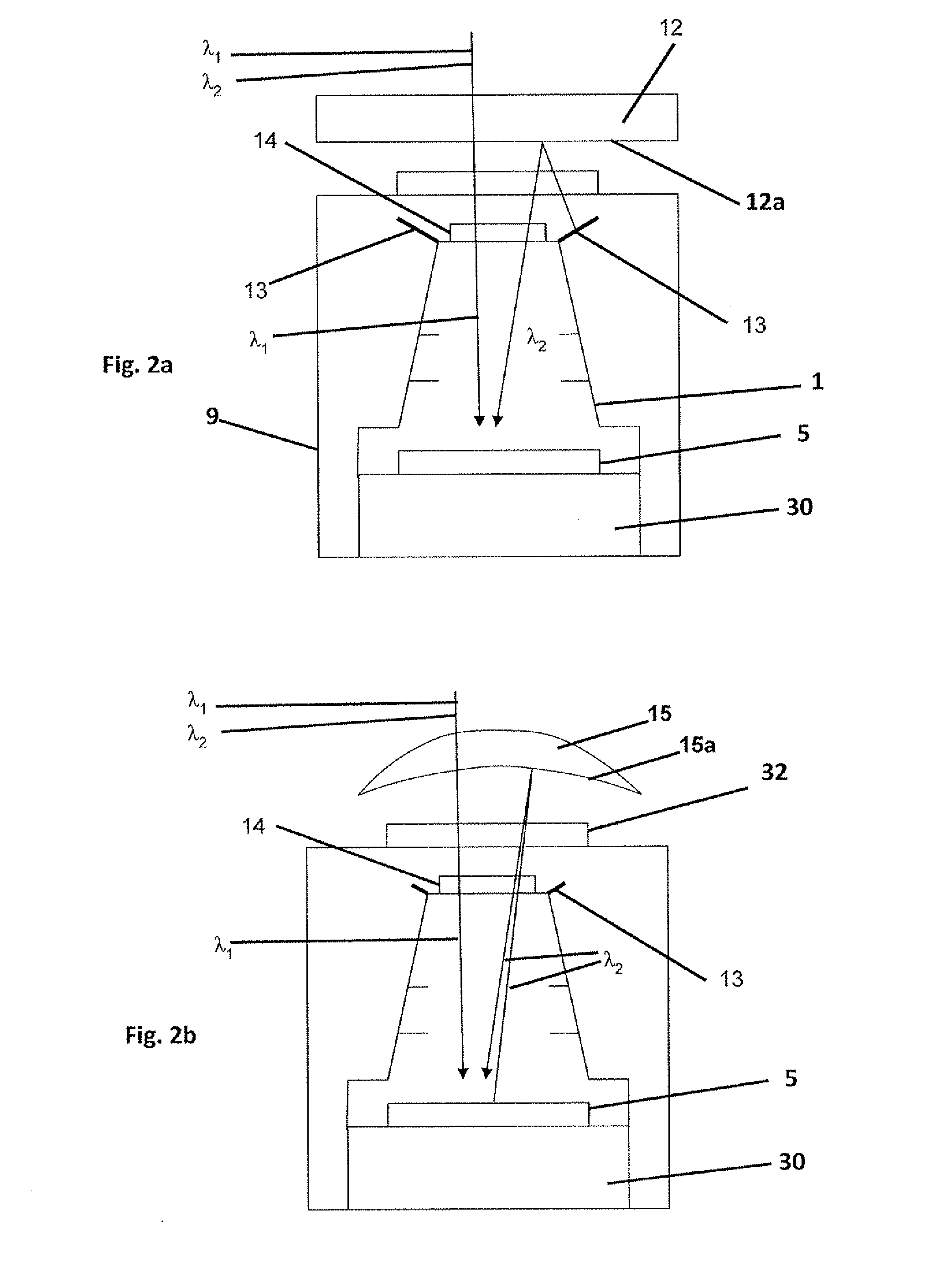
[0016]It is provided according to some embodiments of the current invention, a method for changing an operational spectral range of a cryogenically cooled infra-red detecting device. The method includes a step of allowing transfer to the detector of incoming radiation at a desired spectral range, a step of preventing transfer thereof at an undesired spectral range, and a step of providing a reflecting field of view at the undesired spectral range directed towards at least one cold surface.

Problems solved by technology

It is also problematic to employ moving parts within the vacuum due to generation of dust and problems of lubrication.
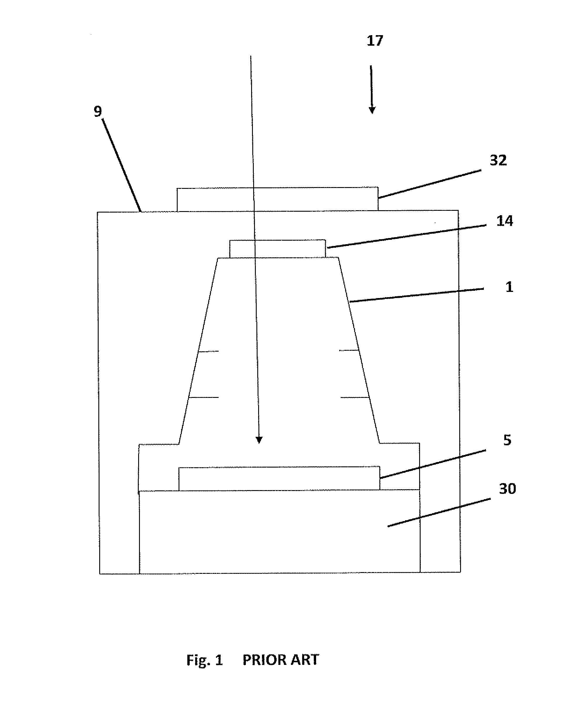
According to the conventional approach, it is assumed that any location of the spectral filter outside Dewar 9 would lead to problematic noise and degradation of the images due to thermal emissions from the filter itself and / or thermal energy from the environment incident on the detector side of the filter and reflected onto a detector or a detector array 5.

Method used


Image

  • System and method for changing spectral range of a cryogenically cooled detector
  • System and method for changing spectral range of a cryogenically cooled detector
  • System and method for changing spectral range of a cryogenically cooled detector

Examples


Embodiment Construction

[0031]The present invention will now be described in terms of specific example embodiments. It is to be understood that the invention is not limited to the example embodiments disclosed. It should also be understood that not every feature of the methods and systems handling the described device is necessary to implement the invention as claimed in any particular one of the appended claims. Various elements and features of devices are described to fully enable the invention. It should also be understood that throughout this disclosure, where a method is shown or described, the steps of the method may be performed in any order or simultaneously, unless it is clear from the context that one step depends on another being performed first.

[0032]Before explaining several embodiments of the invention in detail, it is to be understood that the invention is not limited in its application to the details of construction and the arrangement of the components set forth in the following descriptio...


PUM


Abstract

It is provided an optical system for changing a spectral range of a cryogenically cooled detector. The optical system allows selective spectral transfer of radiation, and provides a reflecting field of view at an undesired range directed towards cold surfaces. A removable spectral filter having a high transmittance at a first spectral range and a low transmittance at a second spectral range is disposed outside a cold shield. A reflective surface faces the detecting device and provides the detector a reflecting field of view at the second spectral range directed towards the cold shield, and a blackened cold skirt thereof. Alternatively, a dichroic mirror is disposed inside the cold shield and has a high reflectance at a first spectral range and a high transmittance at a second range. The detecting device includes a first arm and a second arm of the cold shield to accommodate respective optical channels. A removable selective mirror having a high reflectance at the first spectral range is disposed outside the cold shield. A reflecting field of view at the undesired spectral range directed towards a blackened surface of the cold shield or a thermo-electric cooler is provided.

Description

CROSS REFERENCE[0001]The current application claims the priority rights of Israeli patent application No. 204,025 entitled “CHANGING SPECTRAL RANGE OF CRYOGENICALLY COOLED DETECTOR” filed Feb. 18, 2010, by the current inventor.BACKGROUND OF THE INVENTION[0002]1. Field of the Invention[0003]The invention is in the field of infra-red cryogenically cooled detectors, used to image thermal objects disposed in certain field of view. In special, the current application deals with changing detected spectral range by actions done outside cold shield of the detector.[0004]2. Description of Related Art[0005]An infra-red cryogenically cooled detecting device 17 of the prior art is illustrated in FIG. 1. An infra-red detector 5 is disposed on a cold finger 30, and placed within a cold shield 1. A cold filter 14 is thermally coupled to cold shield 1, and filters the radiation outside the detecting range of detector 5 to prevent undesired heating of the detector. Cold filter 14 may have even a sma...

Claims


Application Information

Patent Timeline
IPC IPC(8): G01J5/06
CPCG01J5/06G01J5/061G01J5/602G01J5/0809G01J5/084G01J5/08G01J5/0808
Inventor YAACOBI, AMI
Owner RAFAEL ADVANCED DEFENSE SYSTEMS
Learn More